® PETROL LAWNMOWER FBM 575 B1 PETROL LAWNMOWER Translation of original operation manual BENZIN-RASENMÄHER Originalbetriebsanleitung IAN 93561 93561_flo_Benzin-Rasenmaeher_cover_GB.indd 2 21.11.
Before reading, unfold the page containing the illustrations and familiarise yourself with all functions of the device. Klappen Sie vor dem Lesen die Seite mit den Abbildungen aus und machen Sie sich anschließend mit allen Funktionen des Gerätes vertraut. GB / IE DE / AT / CH Translation of original operation manual Originalbetriebsanleitung 93561_flo_Benzin-Rasenmaeher_cover_GB.indd 3 Page Seite 21.11.
1 2 3 4a 4b 27 5 6 26 25 7 8 10 11 12 13 14 9 24 23a 15 16 23 22 20 21 28 28a 29 19 18 30 17 31
5 32 2 27 2 3 25 26 5 23 6 26 19 33 8 23a 32 33 37 36 34 22 35 7 9 28a 28 7
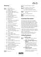
GB IE Content Introduction.................................. 6 Intended Use................................. 6 General Description....................... 6 Delivery Contents.............................. 6 Summary......................................... 7 Functional Description........................ 7 Safety Equipment.............................. 7 Technical Specifications................. 8 Symbols and icons........................ 9 Symbols on the device ......................
GB IE Introduction Congratulations on the purchase of your new device. With it, you have chosen a high quality product. During production, this equipment has been checked for quality and subjected to a final inspection. The functionality of your equipment is therefore guaranteed. It cannot be ruled out that residual quantities of water or lubricants will remain on or in the equipment/hose lines in isolated cases. This is not a fault or defect and it represents no cause for concern.
GB Summary 1 2 3 4a 4b 5 6 7 8 9 10 11 12 13 14 15 16 17 18 19 20 21 22 23 23a 24 25 26 27 28 28a 29 30 31 Drive catch Upper handle bar Safety catch Bowden cable lock nut Bowden cable adjusting nut 2 lower bars Cable clamp Rear impact protection Bowden cables Oil filler cap with dipstick Exhaust guard Filler cap Engine cover with ventilation holes (finger protection) Air filter box Air filter (no illustration) Spark plug connector Spark plug (no illustration) 2 front wheels Sheet steel housing 2 screws and
GB IE Technical Specifications Engine............ 4-stroke B&S 575 EX Series B&S Engine design number...............09P7 Engine size................................ 140 cm3 Power input................................. 2.1 kW Blade rotation speed................2900 min-1 Blade torque............................ 35-45 Nm Wheel drive......................max. 3.8 km/h Petrol tank volume............................ 0.8 l Octane rating................................ 95-98 Engine oil tank volume..............
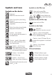
GB Symbols and icons Symbols on the device Attention! Read the instruction manual. Risk of injury from parts being flung out. Keep bystanders away from the equipment. Risk of injury from sharp blades. Keep feet and hands away. Caution – toxic fumes! Do not operate the equipment in enclosed areas. Caution – petrol is flammable! Do not smoke and keep away from heat sources. Caution – risk of injury! Before maintenance work, switch off the engine and take out the spark plug connector.
GB IE Symbols in the manual Warning symbols with information on damage and injury prevention. • Instruction symbols (the instruction is explained at the place of the exclamation mark) with information on preventing damage. • Help symbols with information on improving tool handling. Safety Instructions This section deals with the basic safety procedures when working with the equipment. WARNING! Read all of the safety instructions and directions.
GB • • • • Replace defective silencers. Before use, always carry out a visual inspection to check whether the cutting tools, mounting bolts and entire cutting unit are worn or damaged. To avoid imbalance, only replace worn or damaged tools and bolts in sets. Take care with equipment that has several cutting tools, as the movement of one blade may result in rotation of other blades. Use only replacement parts and accessories supplied and recommended by the manufacturer.
GB • • • • IE ing obstructions in the ejection channel; - Before checking, cleaning or working on the equipment; - If a foreign body is struck. Look for damage to the equipment and carry out the necessary repairs before restarting and working with the equipment; - If the equipment starts to vibrate unusually strongly, an immediate check is required.
GB Mounting grip rod Caution! When installing the handle bar, ensure that the Bowden cables ( 8) are not squashed. Mount lower bars: 1. Position the pins of the lower bar (5) in the boreholes of the bar support (32) (see small image). Make sure that the bar with the starter cable-guide (26) is positioned on the correct side. 2. Screw the lower grip bar (5) tight with the enclosed screws and the wing nuts (19) both right and left of the bar support (32). Three positions are possible.
GB IE Installing the Mulch Kit The grass collection box must be removed before using the mulch kit (see “Installing the Grass Collection Box”) Fixing the Mulch Kit: 1. Lift the impact protection (7). 2. Remove the grass collection box ( 22) if it is installed. 3. Push down the button (28a) on the mulch kit and plug in the mulch kit (28). The button clicks into place. Removing the Mulch Kit: 4. Lift the impact protection (7). 5. Push down the button (28a) and remove the mulch kit (28).
GB Operation (2). The mower moves forwards. 3. Wheel drive off: release the drive catch (1). The equipment stops. Observe the noise protection and local regulations. Starting and Stopping the Engine Warning! Petrol is flammable. Start the engine at least 3 m away from the filling location. There is a risk of fire. Start the equipment on a sturdy, level base, if possible not in long grass. Ensure that the cutting tool is touching neither objects nor the ground.
GB IE The correct cutting height is around 30 – 45 mm for an ornamental lawn and around 40 – 65 mm for a utility lawn. Select a greater cutting height for the first cut of the season. Emptying the Grass Collection Box Fill Level Indicator: The fill level indicator ( 22) attached to the side of the grass collection box ( 24) shows when the grass collection box is full. Fill level indicator open: Grass collection box empty Fill level indicator closed: Grass collection box full 1.
GB Do not tilt the equipment sideways or forwards. Operating fluids could leak out and the engine could be damaged. • • • • • Always keep the equipment clean. To clean, use a toothbrush or cloth but no corrosive cleaning agents or solvents. Do not use water to clean the engine as it could contaminate the fuel system. After mowing, remove plant remains that are stuck to the equipment by using a piece of wood or plastic. Clean the vent holes ( 12), ejection hole and blade area especially.
GB IE (recommended torque 20 Nm, determined with a torque wrench) (see “Replacement parts/Accessories“). Changing the Engine Oil Change the engine oil with the petrol tank empty and the engine warm. • Change the engine oil for the first time after around 5 operating hours then every 50 operating hours or annually. • Dispose of the used oil in an ecofriendly manner (see “Disposal/Environmental protection“). 1. Remove the spark plug connector ( 15). 2.
GB IE Maintenance Intervals Regularly carry out the maintenance work listed in the “maintenance intervals” table. Regular maintenance prolongs the life of the equipment. It also gives optimum cutting performance and avoids accidents. Maintenance Work (See “cleaning and maintenance“) Check and tighten screws, nuts and bolts Check the engine oil level/petrol level and refill with engine oil/ petrol if required Clean operating elements / the area around the silencer Before After Work After 1st 5 Hrs.
GB IE Storage • General Storage Instructions Do not store the equipment with a full collection box. In hot weather, the grass begins to ferment when heat is generated. Risk of fire. • • • • • Clean and service the equipment before storage. Allow the engine to cool before storing the equipment in enclosed areas. Use suitable and authorised containers for storing fuel. Keep the equipment in a dry place that is protected from dust and out of reach of children.
GB IE Replacement parts/Accessories Spare parts and accessories can be obtained at www.grizzly-service.eu If you do not have internet access, please contact the Service Centre (see “Sercice-Center” page 24). Please have the order number mentioned below ready. Pos. Instruction Manual Pos. Exploded Drawing 1/2/3 S-01 Description Order No.
GB IE Troubleshooting Problem Possible Cause Fault Correction Too little petrol in the tank Fill with petrol Follow the instructions for starting the engine (see ”operation“) Attach the spark plug connector Clean, adjust or replace the spark plug (see “cleaning and maintenance“) Have the carburettor adjusted by a specialist workshop Replace the air filter (see “cleaning and maintenance“) Have the carburettor adjusted by a specialist workshop Have the carburettor adjusted by a specialist workshop Clean
GB Guarantee Dear Customer, This equipment is provided with a 3-year guarantee from the date of purchase. Please note any different guarantee conditions for the motor and read the enclosed operating instructions from motor manufacturer “Briggs & Stratton” carefully. This guarantee does not affect your legal guarantee rights. In case of defects, you have statutory rights against the seller of the product. These statutory rights are not restricted by our guarantee presented below.
GB • IE fects occur, please initially contact the service department specified below by telephone or by e-mail. You will then receive further information on the processing of your complaint. After consultation with our customer service, a product recorded as defective can be sent postage paid to the service address communicated to you, with the proof of purchase (receipt) and specification of what constitutes the defect and when it occurred.
DE AT CH Inhalt Einleitung.................................... 26 Verwendungszweck.................... 26 Allgemeine Beschreibung............ 26 Lieferumfang.................................. 26 Übersicht....................................... 27 Funktionsbeschreibung..................... 27 Schutzeinrichtungen........................ 27 Technische Daten......................... 28 Bildzeichen/Symbole................... 29 Bildzeichen auf dem Gerät............... 29 Symbole in der Betriebsanleitung......
DE AT CH Einleitung Herzlichen Glückwunsch zum Kauf Ihres neuen Gerätes. Sie haben sich damit für ein hochwertiges Gerät entschieden. Dieses Gerät wurde während der Produktion auf Qualität geprüft und einer Endkontrolle unterzogen. Die Funktionsfähigkeit Ihres Gerätes ist somit sichergestellt. Es ist nicht auszuschließen, dass sich in Einzelfällen am oder im Gerät, bzw. in Schlauchleitungen Restmengen von Wasser oder Schmierstoffen befinden. Dies ist kein Mangel oder Defekt und kein Grund zur Besorgnis.
DE Übersicht 1 2 3 4a 4b 5 6 7 8 9 10 11 12 13 14 15 16 17 18 19 20 21 22 23 23a 24 25 26 27 28 28a 29 30 31 Antriebsbügel Oberer Griffholm Sicherheitsbügel Feststellmutter Bowdenzug Einstellmutter Bowdenzug 2 untere Holme Kabelklemme Hinterer Prallschutz Bowdenzüge Öltankkappe mit Ölmessstab Auspuffschutz Tankdeckel Motorabdeckung mit Lüftungsöffnungen (Fingerschutz) Luftfilterbox Luftfilter (nicht sichtbar) Zündkerzenstecker Zündkerze (nicht sichtbar) 2 Vorderräder Stahlblechgehäuse 2 Schrauben und 2 Flü
DE AT CH Technische Daten Motor................ 4-Takt B&S 575 EX Series B&S Motor-Modellnummer.................09P7 Motorhubraum............................ 140 cm3 Leistungsaufnahme....................... 2,1 kW Leerlaufdrehzahl (n0).................2900 min-1 Anzugsdrehmoment Messer....... 35-40 Nm Radantrieb........................max. 3,8 km/h Volumen Benzintank......................... 0,8 l Oktanzahl..................................... 95-98 Volumen Motoröltank......................
DE Bildzeichen/Symbole Bildzeichen auf dem Gerät Vorsicht! Betriebsanleitung lesen. Verletzungsgefahr durch weggeschleuderte Teile. Umstehende Personen von dem Gerät fernhalten. Verletzungsgefahr durch scharfe Messer! Füße und Hände fernhalten. Vorsicht - Giftige Dämpfe! Gerät nicht in geschlossenen Räumen betreiben. Vorsicht - Benzin ist brennbar! Nicht rauchen und Wärmequellen fernhalten. Vorsicht Verletzungsgefahr! Vor Wartungsarbeiten Motor ausschalten und Zündkerzenstecker ziehen.
DE AT CH Symbole in der Betriebsanleitung Gefahrenzeichen mit Angaben zur Verhütung von Personen- oder Sachschäden. Gebotszeichen (anstelle des Ausrufungszeichens ist das Gebot erläutert) mit Angaben zur Verhütung von Schäden. Hinweiszeichen mit Informationen zum besseren Umgang mit dem Gerät. Sicherheitshinweise Dieser Abschnitt behandelt die grundlegenden Sicherheitsvorschriften bei der Arbeit mit dem Gerät. Warnung! Lesen Sie alle Sicherheitshinweise und Anweisungen.
DE • • • • nachgefüllt werden. - falls Benzin übergelaufen ist, darf kein Versuch unternommen werden, den Motor zu starten. Stattdessen ist das Gerät von der benzinverschmutzten Fläche zu entfernen. Jeglicher Zündversuch ist zu vermeiden, bis sich die Benzindämpfe verflüchtigt haben; - aus Sicherheitsgründen sind Benzintank- und andere Tankdeckel bei Beschädigung auszutauschen. Ersetzen Sie defekte Schalldämpfer.
DE • • • • • • • • 32 AT CH heben Sie nur die vom Benutzer abgewandte Seite hoch. Starten Sie den Motor nicht, wenn Sie vor der Auswurföffnung stehen. Schalten Sie den Motor nach Anweisung ein und nur dann, wenn Ihre Füße in sicherem Abstand von den Schneidwerkzeugen sind. Führen Sie niemals Hände oder Füße an oder unter sich drehende Teile. Halten Sie sich immer entfernt von der Auswurföffnung. Ein Moment der Unachtsamkeit bei Benutzung des Gerätes kann zu schweren Verletzungen führen.
DE • nur von Kundendienststellen ausgeführt werden, die von uns ermächtigt sind. Bewahren Sie das Gerät an einem trockenen Ort und außerhalb der Reichweite von Kindern auf. Geräte sind gefährlich, wenn sie von unerfahrenen Personen benutzt werden. AT CH (5) mit den beiliegenden Schrauben und den Flügelmuttern (19) rechts und links an die Holmaufnahme (32) an. Es sind drei Positionen möglich. Oberen Griffholm montieren: 3.
DE AT CH Tragegriff montieren: 1. Setzen Sie den Tragegriff (23) auf die Hartschale (33) des Grasfangkorbs auf und schrauben Sie ihn von unten mit den beiden Kreuzschlitzschrauben (23a) fest. Fangnetz montieren 2. Klipsen Sie die Gummilippen am Fangkorbnetz (34) in die Hartschale (33) des Grasfangkorbs ein. 3. Stülpen Sie die Kunststoff-Laschen (35) über das Rohrgestell (36). Grasfangkorb am Gerät anbringen: 1. Heben Sie den hinteren Prallschutz (7) an. 2.
DE Benzin einfüllen AT CH Bedienung Beachten Sie den Lärmschutz und örtliche Vorschriften.
DE AT CH Mähen 1. Starten Sie den Motor (siehe „Motor starten und stoppen“). 2. Radantrieb ein: Ziehen Sie den Antriebsbügel (1) in Richtung Griffholm (2), das Gerät bewegt sich nach vorn. 3. Radantrieb aus: Lassen Sie den Antriebsbügel (1) los. Das Gerät bleibt stehen. Arbeitshinweise Allgemeine Arbeitshinweise • • • • • • • • 36 Mähen Sie möglichst trockenen Rasen, um die Grasnarbe zu schonen. Stellen Sie die Schnitthöhe so ein, dass das Gerät nicht überlastet wird.
DE Mähen mit dem Mulchkit Beim Mulchmähen wird das Gras in einem Arbeitsgang geschnitten, klein gehäckselt und auf dem Rasen verteilt. Das geschnittene Gras dient als natürlicher Dünger. Tipps zum Mulchmähen: • Zurückschneiden des Grases um 2 cm bei 4-6 cm Grashöhe. • Scharfe Schneidmesser verwenden. • Kein nasses Gras mähen. Tragen Sie beim Umgang mit dem Messer Handschuhe. Beachten Sie für Reinigungs- und Wartungsarbeiten auch die mitgelieferte Betriebsanleitung von Briggs & Stratton.
DE • AT CH Überprüfen Sie Abdeckungen und Schutzeinrichtungen ( 3, 7, 10, 12) auf Beschädigungen und korrekten Sitz. Tauschen Sie diese gegebenenfalls aus. Messer reinigen Die Messer und die Geräteunterseite lassen sich einfach über den Gartenschlauchanschluss (39) mit Wasser reinigen, ohne das Gerät zu kippen. 1. Stellen Sie das Gerät auf eine ebene Fläche. 2. Schließen Sie einen Gartenschlauch mit einem herkömmlichen Schlauchkupplungssystem an den Gartenschlauchanschluss (39) an. 3.
DE Motoröl wechseln Führen Sie den Motorölwechsel bei leerem Benzintank und warmem Motor durch. • Führen Sie den ersten Motorölwechsel nach etwa 5 Betriebsstunden, danach alle 50 Betriebsstunden oder jährlich durch. • Entsorgen Sie das Altöl umweltgerecht (siehe „Entsorgung/ Umweltschutz“). 1. Ziehen Sie den Zündkerzenstecker ab ( 15). 2. Öffnen Sie die Öltankkappe ( 9) und pumpen Sie das Motoröl mit einer Ölpumpe ab. 3. Füllen Sie Motoröl nach (siehe „Inbetriebnahme“).
DE AT CH Wartungsintervalle Führen Sie die in der Tabelle aufgeführten Wartungsarbeiten regelmäßig durch. Durch regelmäßige Wartung wird die Lebensdauer des Gerätes verlängert. Sie erreichen zudem optimale Schnittleistungen und vermeiden Unfälle.
DE Lagerung Allgemeine Lagerungshinweise Lagern Sie das Gerät nicht mit gefülltem Grasfangkorb. Bei heißem Wetter beginnt das Gras unter Wärmeentwicklung zu gären. Es besteht Brandgefahr. • • • • • Reinigen und warten Sie das Gerät vor der Lagerung. Lassen Sie den Motor abkühlen, bevor Sie das Gerät in geschlossenen Räumen abstellen. Verwenden Sie zur Aufbewahrung des Kraftstoffs geeignete und zulässige Behälter.
DE AT CH Entsorgung/ Umweltschutz • • • 42 Führen Sie Gerät, Zubehör und Verpackung einer umweltgerechten Wiederverwertung zu. - Entleeren Sie den Benzin- und Öltank sorgfältig und geben Sie Ihr Gerät an einer Verwertungsstelle ab. Die verwendeten Kunststoff- und Metallteile können sortenrein getrennt werden und so einer Wiederverwertung zugeführt werden. - Geben Sie Altöl und Benzinreste an einer Entsorgungsstelle ab und schütten diese nicht in die Kanalisation oder in den Abfluss.
DE AT CH Ersatzteile/Zubehör Ersatzteile und Zubehör erhalten Sie unter www.grizzly-shop.de oder www.grizzly-service.eu. Sollten Sie kein Internet haben, so wenden Sie sich bitte telefonisch an das ServiceCenter (siehe „Service-Center“ Seite 46). Halten Sie die unten genannten Bestellnummern bereit. Position Betriebsanleitung Position Explosionszeichnung Bezeichnung 1/2/3 S-01 Oberer Griffholm/Kappe ob. Griffholm Sicherheitsbügel/Antriebsbügel Bestell-Nr.
DE AT CH Fehlersuche Problem Mögliche Ursache Fehlerbehebung Zu wenig Benzin im Benzintank Benzin einfüllen Falsche Startreihenfolge Motor startet nicht Zündkerzenstecker ( 15) nicht richtig aufgesteckt Verrußte Zündkerze Anweisungen zum Starten des Motors beachten (siehe „Bedienung“) Zündkerzenstecker aufstecken Zündkerze reinigen, einstellen oder ersetzen (siehe „Reinigung und Wartung“) Vergaser durch eine Fachwerkstatt einstellen lassen Luftfilter ersetzen (siehe „Reinigung und Verschmutzter L
DE Garantie Sehr geehrte Kundin, sehr geehrter Kunde, Sie erhalten auf dieses Gerät 3 Jahre Garantie ab Kaufdatum. Bitte beachten Sie gegebenenfalls unterschiedliche Garantiebedingungen für den Motor und lesen Sie dazu sorgfältig die beiliegende Betriebsanleitung des Motorherstellers „Briggs & Stratton“. Ihre gesetzlichen Gewährleistungsansprüche werden von dieser Garantie nicht beeinträchtigt. Im Falle von Mängeln dieses Gerätes stehen Ihnen gegen den Verkäufer des Gerätes gesetzliche Rechte zu.
DE • • • AT CH den Kauf bereit. Die Artikelnummer entnehmen Sie bitte dem Typenschild. Sollten Funktionsfehler oder sonstige Mängel auftreten, kontaktieren Sie zunächst die nachfolgend benannte Serviceabteilung telefonisch oder per E-Mail. Sie erhalten dann weitere Informationen über die Abwicklung Ihrer Reklamation.
DE AT CH Original EG-Kon- GB formitätserklärung IE Translation of the original EC declaration of conformity Hiermit bestätigen wir, dass der Benzin-Rasenmäher Baureihe FBM 575 B1 We herewith confirm that the Petrol lawn mower Series FBM 575 B1 Seriennummer 201311000001 - 201402006668 Serial number 201311000001 - 201402006668 folgenden einschlägigen EU-Richtlinien in ihrer jeweils gültigen Fassung entspricht: is compliant with the current versions of the following relevant EU guidelines: 2006/42/EC
Explosionszeichnungen • Exploded Drawings FBM 575 B1 informativ, informative 48
2013-12-18_rev02_gs 49 informativ, informative FBM 575 B1
3 2 1 25 26 20 39 38 14 0,51 mm 16 15 13 4a 4b 19 8 2 5 27
GRIZZLY GARTENGERÄTE GMBH & CO. KG Am Gewerbepark 2 D-64823 Groß-Umstadt Last Information Update Stand der Informationen: 11 / 2013 Ident.-No.: 89420207112013-6 IAN 93561 93561_flo_Benzin-Rasenmaeher_cover_GB.indd 1 6 21.11.