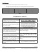
Installation / Troubleshooting Manual TWINSCAN 3”, GAS AND DIESEL TACH (New LCD) This manual (part # 1000-158-01) applies to the following product part numbers: 1) 2) 3) 4) 5) 6) 7) 8) 9) 10) 11) 12) 13) 14) 15) 16) 17) 18) 19) 20) 21) 22) 23) 24) 25) 26) 27) 28) 3TB013U 3TB014M 3TB014U 3TB016M 3TB016U 3TB018M 3TB018U 3TB023M 3TB024U 3TB026U 3TB028U 3TS013M 3TS013U 3TS014U 3TS016U 3TS023U 3TS024M 3TS024U 3TS026M 3TS026U 3TS028U 3TW023M 3TW023U 3TW024M 3TW024U 3TW026M 3TW026U 3TW028U 3/8/2000 FloScan Ins
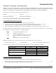
TROUBLESHOOTING ® TwinScan 3” Instrument - Tachometer (LCD) BEFORE CALLING FOR ASSISTANCE, COMPLETE THESE TROUBLESHOOTING CHECKS AND RECORD YOUR FINDINGS. TECHNICAL SUPPORT REQUIRES THIS INFORMATION BEFORE A RETURN AUTHORIZATION WILL BE ISSUED. IT TAKES ABOUT 20 MINUTES AND IS VERY IMPORTANT IN ANALYZING SYSTEM PROBLEMS. Before starting, record instrument model number and switch settings.
• • If 12 VDC is not present, measure between the RED, or RED/WHITE power wire and a known good ground in the instrument panel. If you measure 12 to 14 VDC there may be an instrument ground problem. __________VDC If 12 to 14 VDC is not present check wiring, switches, fuse, and the 12 VDC power source. III. CONTINUITY TEST • Continuity testing requires access to the back of the Instrument and an Ohmmeter. It verifies that wires are not broken, shorted to ground, another wire, or to power.
! INSTALLATION PLANNING ! READ ME FIRST - Mechanical & Electrical Installation Planning Saves Time! FloScan systems are not difficult to install. Installing one requires only basic electrical & mechanical skills. With forethought and planning, your system will be installed with few problems. I. Installation Preparation: Review the mechanical installation instructions, then survey your vessel. Determine where the Sensor(s), Pulsation Damper(s), (if used) Switches and Instruments are to be mounted.
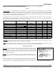
VI. Calibration: When system is running properly, refer to the calibration instructions and calibrate your system. USCG approved fuel hose with either fabric or wire reinforcing braid meet the following standards: Hose Marking USCG Type A-1 USCG Type A-2 USCG Type B-1 USCG Type B-2 Permeation Rating 100g/m²/24hrs. 300g/m²/24hrs. 100g/m²/24hrs. 300g/m²/24hrs.
OPERATION TwinScan 3” Tachometer (LCD) To ensure years of trouble free operation of your new TwinScan instrument, please read all of these instructions carefully before beginning your installation. 1. Mounting Location TwinScan instruments allow you to quickly monitor and compare port and starboard engine performance. The front faces of all TwinScan® instruments are water-resistant and include a gasket to seal the instrument to the panel.
The number of bars visible in the display indicates how far the engines are out of synch. Referring to the gas engine settings in the chart below, the display shows one vertical line if the engines are within 200 rpm (coarse) or 100 rpm (fine); it will only indicate “IN SYNCH” if the engines are within 100 and 50 for the coarse and fine resolution respectively.
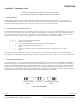
INSTALLATION / WIRING TwinScan 3” Instrument – Tachometer & GPH Gas– NMEA 0183 Input (LCD) ****************************** *COMBINATION ONLY* ****************************** This unit conforms to NMEA 183, Version 1.5 and 2.0 interface standards, and requires a message that includes “VTG”, “RMC” or “RMA”. Check your owner’s manual to verify your GPS / LORAN-C includes this information. To insure an easy trouble free installation, read all instructions before starting. WIRING 1.
Note: THIS SHEET IS TO BE USED ONLY WHEN INSTALLING A TWINSCAN GPH METER AND TACHOMETER COMBINNED.
ELECTRICAL Series 5400(0)/5500(0)/56100/5800(0)/6500(0)/6600(0) AccuTroll & CruiseMaster, All Multi Function Instruments, & TwinScan® SET UP Wire & Switches: Use 18 AWG stranded wire on runs under 50’. For runs over 50’ use 16 AWG. Shielded wire is recommended for all Diesel systems and suggested for Inboard & I/O gasoline systems. Always, “Ground” the wire shield or shield drain wires in the engine room by connecting them to the bonding system or engine block.
Tachometer Wiring Information applies only to MFI & TwinScan Instrument Tachometers Tachometer signal wires on MFI & TwinScan Tachometers should be shielded. For proper tachometer operation on gasoline EFI engines, (especially outboards) the engine Ground wire must be physically connected to the MFI or TwinScan instrument ground wire. Note: FloScan recommends using dedicated 18 AWG shielded cable for tachometer signal wire connections.
ELECTRICAL TwinScan Gas & Diesel Tachometer Tachometer Wiring: For proper tachometer operation on Gasoline EFI engines, (especially outboards) the engine Ground wire must be directly connected to the TwinScan Tachometer ground wire. FloScan recommends using dedicated 18 AWG shielded cable for tachometer signal wire connections. Always, “Ground” wire shield or shield drain wire in the engine room by connecting it to the bonding system, or engine block.
WIRING Installation Instructions TwinScan® 3” Instrument – Tachometer Only Gas and Diesel Engines To ensure years of trouble free operation of your new TwinScan Instrument please read all of these instructions carefully before beginning your installation. CAUTION: To avoid electrical shorts and possible fire, turn OFF the power to the instrument panel until installation is complete. WIRING Use No. 18 AWG multi-strand wire, the included butt splices, and self-sealing heat shrink to make all connections.
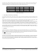
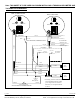
WIRING SCHEMATIC FOR GAS AND DIESEL TWINSCAN TACHOMETER Wiring Schematic For Gas Twinscan Tachometer Back of Tachometer YELLOW + 12VDC Distributor Coil VIOLET Distributor Coil + 12VDC 0 0 Black Switch Red Switch Starboard Keyswitch RED + 12V CABLE + 12V BLACK 1/2 amp fuses RED/WHITE Port Keyswitch (Used with TwinScan GPH instrument ) WHITE/ORANGE Tape End GREEN/BLACK Battery Post Negative Wiring Schematic For Diesel Twinscan Tachometer Tape End BLUE Tape End Back of Tachometer P
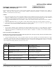
CALIBRATION TwinScan 3” Instrument – Tachometer (LCD) Diesel Engines Back of Instrument Dial Lamp The TwinScan 3” Tachometer is unique in that it can be calibrated for both gasoline and diesel systems. On the back of the TwinScan 3” Tachometer Instrument, the RED switch is used for fine calibration. The BLACK switch is used for coarse calibration. You will use a combination of both switches for proper calibration.
III. ALTERNATOR The alternator input usually comes off one of the windings of the alternator before it is rectified. This tachometer signal is inconsistently inaccurate because of a varying amount of belt slippage depending on the load on the alternator, the dimension of the belt and the belt tension. Calibration You can calibrate the tachometer by two methods: 1. Calibrate to the existing tachometer.
CALIBRATION TwinScan 3” Instrument – Tachometer (LCD) Gasoline Engines Back of Instrument Dial Lamp TwinScan 3” Tachometers are unique in that they can be used on gasoline and diesel engines. For gasoline engine calibration refer to the appropriate engine section, Inboard or Outboard. 0 Black Switch 0 Calibration Knobs Red Switch Wires There are two calibration switches on the back of the instrument, Black and Red. Both are required for calibration.
Outboard Engines: Tachometer calibration for standard point and electronic ignition outboard engines is usually based upon the number of alternator pole pairs. EFI outboards sometimes use a CPU to generate its tachometer signal. Calibration for EFI engines is not always based alternator pole pairs. Refer to your engine manual or check with a local dealer to determine the number of alternator pole pairs your engine has.