
Use and Care Manual


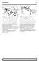


Component Reference and Brush Installation 6
For parts or assistance, call Flotec Customer Service at 1-800-365-6832
Brush must enter
square hole.
Match brush curve
to armature curve
12
345678910
11 12
Ref. Description
1 10-32x1-3/4 Phil. Hd Screw*
2 End Cover / Wear Plate
3 O-Ring
4 Impeller
5 Insert
6 U Cup Seal
7 Pump Body
8 Slinger
9 Motor**
10 Motor Brush Set (1 Pair)
11 Screen, Suction (S8-146)
12 Pud-L-Scoop®
* Standard hardware item; purchase locally.
** If motor fails, replace entire pump.
Pu mp Head Assembly No. RP4940-22 includes Ref. Nos.
1 through 8.
Im peller and Seal Kit No. FP003414S-01 includes 1 each
of Ref. Nos. 3, 4, and 6.
Re f. 10 Brush Kit No. FP003415S includes a pair of
replaceable brushes, springs, and caps.
Pu d-L-Scoop® No. FP000349A includes a 6’ garden hose
with washer.