
Product Manual


INSTALLATION WIRING INSTRUCTIONS
Single Phase, 3 Wire
Hazardous voltage. Can shock, burn, or kill.
Ground control box, all metal plumbing, and motor frame with cop-
per wire in compliance with Canadian Electrical Code or National
Electrical Code and local codes. Use ground wire at least as large
as the wires supplying power to motor.
At well head, connect ground wire to grounding terminal that meets
Canadian Electrical Code or National Electrical Code requirements
that apply. For more information, contact local code officials.
Permanently close all unused openings in this and other equipment.
Disconnect power before working on or around control box, pipes,
cable, pump, or motor.
NOTICE: Install control box vertically on wall with top side up.
3-Wire pumps have three power supply wires (Red/Black/Yellow)
and one ground wire (Green).
3 wire pumps will not operate without control box, and will burn out
motor.
Installations must include circuit and component protection in com-
pliance with U.S. National Electrical Code or Canadian Electrical
Code, Part 1.
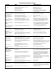
If main overload trips, look for:
1. Shorted Capacitor
2. Voltage Problems
3. Overload or locked pump.
NOTICE: Use only control box specified for your pump. Make
sure motor and control box match (Table 4). FAILURE TO DO
SO WILL VOID WARRANTY. Franklin motor and control box model
numbers may include additional suffix numbers to the right of the
numbers shown here. These additional numbers are not important
for control box selection.
Table 4: Control Box Chart
For motors of 1-1/2 HP and above, use magnetic
starter to avoid damage to pressure switch. Consult factory for
wiring information.
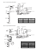
Fig. 1A – 3 wire - 1/2 thru 1 HP quick disconnect box.
Single Phase, 2 Wire
2-Wire pumps have two power supply wires (Red/Black) and one
ground wire (Green). Control box is not required.
See Figure 1B for correct hook-up information for 230 Volt 2-Wire
motors only.
Fig. 1B – Single phase, 2 Wire Connections
Follow color coding when connecting control box.
(Yellow to Y, Red to R, Black to B)
3
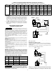
NOTE:
1. Maximum wire lengths shown maintain motor voltage at 95%
of service entrance voltage, running at maximum nameplate
amperes. If service entrance voltage will be at least motor
nameplate voltage under normal load conditions, 50% addi-
tional length is permissable for all sizes.
2. Sizes given are for copper wire. For aluminum wire go two
sizes larger (i.e., if table lists #12 (3mm
2
) copper wire, use #10
(5mm
2
) aluminum wire.)
Volts HP 14 12 10 8 6 4 3 2 1 0
(2mm
2
) (3mm
2
) (5mm
2
) (7mm
2
) (13mm
2
) (21mm
2
) (25mm
2
) (34mm
2
) (41mm
2
) (50mm
2
)
1/2
400 650 1020 1610 2510 3880 4810 5880 7170 8720
(121.9) (198.1) (310.9) (490.7) (765) (1182.6) (1466.1) (1792.2) (2185.4) (2657.9)
3/4
300 480 760 1200 1870 2890 3580 4370 5330 6470
(91.4) (146.3) (231.6) (365.8) (570) (880.9) (1091.2) (1332) (1624.6) (1972.1)
230
1
250 400 630 990 1540 2380 2960 3610 4410 5360
(76.2) (121.9) (192) (301.8) (469.4) (725.4) (902.2) (1100.3) (1344.2) (1633.7)
1.5
190 310 480 770 1200 1870 2320 2850 3500 4280
(57.9) (94.5) (146.3) (234.7) (365.8) (570) (707.1) (868.7) (1066.8) (1304.5)
2
150 250 380 620 970 1530 1910 2360 2930 3620
(45.7) (76.2) (118.9) (189) (295.6) (466.3) (582.2) (719.3) (893.1) (1103.4)
Table 3: Power Supply Wire (Cable) Length in Feet (M)
1 Phase, 2 or 3 Wire Cable, 60 Hz (Copper Wire Size - Service to motor)
HP Voltage Motor No. Control Box No.
1/2 230
214305
28010549
214505
3/4 230
214307
28010749
214507
1 230
214308
28010849
214508
1-1/2 230 224300 28230081
2 230 224301
28230181
28230183
L1 M1
M2L2
Control
box
L1L2R Y B
Fused
disconnect
switch
115V or
230V Line
Ground
Red
Yellow
Black
Pressure
switch
Well
casing
Ground
699 0993
L1 M1
M2L2
Fused
Disconnect
Switch
To Line
Ground
Red
Black
Pressure
Switch
Well
Casing
Ground
(Green)
336 1093