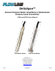
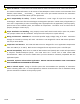
DeltaSpan™ General Purpose Water Small Bore or Wastewater Pressure Level Transmitter LD34 and LD35 Series Manual LD34 Series Shown LD35 Series Shown Flowline, Inc. 10500 Humbolt Street Los Alamitos, CA 90720 Tel: (562) 598‐3015 Fax: (562) 431‐8507 www.flowline.
INTRODUCTION / TABLE OF CONTENTS Step One The DeltaSpan™ LD34 Series General Purpose Water Small Bore or LD35 Series General Purpose Wastewater Level Transmitters are manufactured for years of trouble free service. The pressure transmitter measures the height of liquid above the position in the tank referenced to atmospheric pressure. Lightning and surge protection (not guaranteed or covered by standard warranty) is included standard to stand up in harsh applications.
SPECIFICATIONS Service: Wetted Materials: Accuracy: Temperature Limit: Compensated Temperature Limits: Thermal Effect: Pressure Limit: Power Requirement: Output Signal: Response Time: Max. Loop Resistance: Electrical Connections: Cable Length: Mounting Connection: Electrical Protection: Sensor Weight: Rev B Step Two Compatible liquids Sensor: 316 SS Cable: Polyurethane or ETFE Seals: Fluoroelastomer Diaphragm: PTFE coated FKM fluoroelastomer (LD35 series only) Label: Polyethylene polyamide ±0.
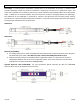
DIMENSIONS Step Three Technology: A sealed pressure transmitter is placed near or on the bottom of the tank. A stainless steel pressure diaphragm within the pressure transmitter is exposed on one side to the application liquid. The other side is exposed to the reference pressure via a small ventilation tube located inside of the Polyurethane cable. A difference in pressure between liquid and reference pressures will slightly deflect the diaphragm.
SAFETY PRECAUTIONS Step Four About this Manual: PLEASE READ THE ENTIRE MANUAL PRIOR TO INSTALLING OR USING THIS PRODUCT. This manual includes information on all versions of the DeltaSpan™ Series Pressure Level Transmitter from Flowline; series LD34‐S___ and LD35‐S___. Please refer to the part number located on the transmitter label to verify the exact model which you have purchased. User’s Responsibility for Safety: Flowline manufactures a wide range of liquid level sensors and technologies.
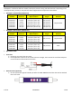
COMPONENTS Step Five DeltaSpan™ is offered in different models, based upon pressure rating and cable material. Depending on the model purchased, you may or may not have been shipped all the components shown below. DeltaSpan™ Submersible (LD34 Series) Part Maximum Range in Number Pressure Water Column LD34‐S101 5.0 psi 11.54 ft wc (3.52 m wc) LD34‐S111 6.5 psi 15.0 ft wc (4.6 m wc) LD34‐S121 8.6 psi 20.0 ft wc (6.1 m wc) LD34‐S131 13.0 psi 30.0 ft wc (9.1 m wc) LD34‐S141 21.6 psi 50.0 ft wc (15.
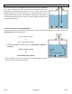
GETTING STARTED Step Six Pressure transmitters are designed to be submersed within the application fluid. The transmitters can either rest along the bottom of the tank or be suspended at any desired level within the tank. Please note that the physical location of the level transmitter will indicate the lowest level of measurement within the tank. For example: mounting the transmitter 1 foot from the bottom of the tank, then the lowest reading of liquid will be 1 foot from the bottom.
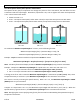
GETTING STARTED (continued) Step Six How does Specific Gravity affect pressure transmitters? The Specific Gravity (SG) of a liquid will not change the pressure of the transmitter, but will affect how the transmitter reads the liquid height. Remember, liquids with a SQ < 1.0 are lighter than water and liquids with a SG > 1.0 are heavier than water. Water has a SG = 1.0. A SG < 1.0 requires more liquid (a taller water column) to equal the same pressure as with water. A SG > 1.
GETTING STARTED (continued) Step Six How to select the correct pressure transmitter? The objective is to select a sensor with an operational range that will cover the entire application span. If the liquid height of the tank is above the sensor’s Maximum Liquid Height, then the sensor will not be able to read a full tank level. Compare the tank’s Pressure @ Full against the sensor’s pressure range to select a sensor.
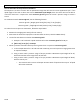
GETTING STARTED (continued) Step Six How to configure a panel meter when a pressure transmitter is used? This method works with the LI55 series, LI25 Series, LI10 Series and LI50 Series. These panel meters are configured using the SCALE function. The SCALE function typically has four settings. These settings are as follows: Settings Default Represents Typical Setting Input 1 04.000 Input current @ Empty 04.000 (mA) Display 1 (Empty) 04.000 Display value @ Empty Empty value Input 2 20.
ELECTRICAL INSTALLATION Step Seven Wire Length ‐ The maximum length of wire connecting the transmitter and receiver is a function of wire size and receiver resistance. Wiring should not contribute more than 10% of the receiver resistance to total loop resistance. For extremely long runs (over 1000 feet), choose receivers with higher resistance to minimize the size and cost of connecting leads. Where wiring length is less than 100 feet, wire as small as 22 AWG can be used.
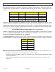
WIRING Step Eight Wiring to a Loop Powered Display: Wiring to a Generic PLC: Wiring to the DataView™ LI55 Series Level Controller: Wiring to the Commander™ LI90 Series Multi‐Tank Level Controller: 12 of 16 MN301035 Rev B
WIRING (continued) Step Eight Wiring to the DataPoint™ LC52 Series Level Controller: JWA mode (Factory Setting) Wiring to a DataLoop™ LI25 Series Level Indicator without the Backlight: (Note: the LI25 series without backlight will have an added 2 VDC voltage drop) Wiring to a DataLoop™ LI25 Series Level Indicator with the Backlight: (Note: the LI25 series without backlight will have an added 5.
INSTALLATION Step Nine The LD34 / LD35 series are designed to operate while submerged in the actual application liquid. Avoid installing the level transmitter along the bottom of the tank as materials such as sludge will build up and coat/cover the transmitter. This also includes any debris that will settle along the bottom of the tank. In these applications, it is best to suspend the transmitter above the highest level of sludge/debris that will occur. 1.
MAINTENANCE Step Ten After final installation of the pressure transmitter and its companion receiver, no routine maintenance is required. A periodic check of system calibration is suggested. The pressure transmitters are not field repairable and should be returned if repair is needed (field repair should not be attempted and may void warranty). Be sure to include a brief description of the problem plus any relevant application notes.
WARRANTY, RETURNS & LIMITATIONS Step Eleven Warranty Flowline warrants to the original purchaser of its products that such products will be free from defects in material and workmanship under normal use and service in accordance with instructions furnished by Flowline for a period of two years from the date of manufacture of such products.