INSTALLATION, OPERATION AND MAINTENANCE MANUAL Warning Please read carefully before proceeding with installation. Your failure to follow a attached instructions or operating parameters may lead to the product's failure and possible damage to property. ******************************************************************************************* Save manual for future reference.
Thank you for your purchase of a Flowmatic Reverse Osmosis system. With proper installation and maintenance, this system will provide you with high quality water for years to come. All of Flowmatic water enhancement products are rigorously tested by independent laboratories for safety and reliability. If you have any questions or concerns, please contact our customer service department at 1-800-461-4406 TABLE OF CONTENTS Operational Parameters ............................................................
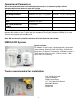
Operational Parameters Do not use with water that is microbiologically unsafe or of unknown quality, without adequate disinfection before or after the system. Operating Temperatures: Maximum 100°F (37.8°C) Minimum 40°F ( 4.4°C) Operating Pressure: Maximum 100 psi (7.43 g/cm2) Minimum pH Parameters: Maximum Iron: Maximum 0.2 ppm TDS (Total Dissolved Solids): Turbidity: < 1000 ppm 11 Minimum 40 psi (2.80 kg/cm2) 3 <5NTU Hardness: Recommended hardness not to exceed 7 grains per gallon, or 120ppm.
Installation of Faucet Caution: Porcelain sink surface material is extremely hard and may crack or chip. Use extreme caution when drilling. Watts accepts no responsibility for damage resulting from the installation of the faucet.
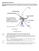
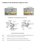
Installation of hot and cold water supply line valves For3/ 8”pl umbi ng For1/ 2”pl umbi ng Hand tighten brass nuts then apply 1/4 turn with a wrench. To RO System 1/4" Compression Nut 1/4" Compression Nut Plastic Sleeve Brass Plastic Sleeve Insert Brass Insert 3/8"M X 1/2"F Adapter Angle Stop Valve (not included) Rubber 1/2"M X 3/8"F X 1/4"Comp. with needle valve Angle Stop Valve (not included) Washer RO Tubes will be connected on page 6.
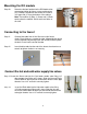
Mounting the RO module Step 10 Determine the best location for the RO Module to be mounted and allow for future system maintenance. Use a Phillips screwdriver and secure the screws 5 3/ 4”apar tand16”f r om t hebot t om oft hec abi net . Note: There will be (2) Blue, (1) Green and (1) Black coming from the module. Do not cut these tubes at this time. Connecting to the faucet Step 11 Connect blue tube from in-line filter over to the faucet shank.
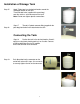
Installation of Storage Tank Step 15 Step 16 Apply Teflon tape in a clockwise direction around the male pipe threads on the tank. Thread the ball valve (supplied in the parts bag) onto the stainless steel connector on the tank. Note: Do not over tighten plastics connections. Step 17 Thr ead1/ 4”pl as t i cc onnec t orf i t t i ng( s uppl i edi nt he parts bag) into the ball valve attached to the tank. Connecting the Tank Step 18 Postion the tank in the desired location.
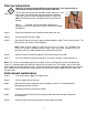
Start up Instructions Warning: To prevent the possibility of electrical shock, clean up any water on cabinet floor and dry all water from outside of RO unit. Step 1 Turn on the incoming hot and cold water angle stop valves. Turn on the water line needle valves by turning counter clockwise. Check the system for leaks and tighten fittings as necessary. Note: Check daily over the next week to ensure no leaks are present.
Semi-annual maintenance continued Step 7 Inspect O-rings for wear and replace them if needed (order part no. WP113029 from Watts.) Lubricate O-rings with a water soluble lubricant such as KY Jelly®, (petroleum based lubricants such as Vaseline® must not be used.) Be sure to properly seat the O-ring in the housing before threading the housings onto the lid assembly.
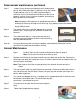
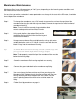
Membrane Maintenance Membrane filters have a life expectancy of 2 to 5 years, depending on the incoming water conditions and the amount of use of the RO system. If at any time you notice a reduction in water production or a change in the taste of the RO water, it could be time to replace the membrane. Step 1 To change the membrane, use a 5/8" wrench to remove the nut from the cap side of the membrane housing (the end with only one elbow). Remove the cap from the white horizontal membrane housing.
Trouble shooting Problem Cause Solution Low/slow production Excessive air pressure in tank Relieve pressure at Schrader valve on tank (set to 7 psi with the tank empty) Pump not operating Fouled membrane Plugged pre-filters Crimped tubing Angle stop or water line valve not fully opened Milky colored water Air in the system Faucet Dripping Pump short cycles Needs adjustment Ball valve on tank closed Blue tube blocked between the tank and RO system Faulty pressure switch Damaged/Dry O-ring Bowl lea
Adjust Faucet If the faucet has developed a drip it can be corrected by following the steps outlined below. Step 1 Remove faucet Spout first. Position both thumbs on the back edge of the lever and push forward. Step 2 Lever will slide forward and completely off of the faucet base. Step 3 Small brass tee can be turned 1/2 turn, counterclockwise, to adjust the tension on the black lever. This adjustment may be necessary to stop slow drips from tip of faucet.
SERVICE RECORD DATE OF PURCHASE / / DATE OF INSTALL / / Date of Maintenance (6 mos.) 2nd stage Carbon Block (6 mos.) 1st stage Sediment INSTALLED BY NAME: (1 yr.) Final Filter Carbon NOTES: 13 (2-5 yrs.) TFM Memb. SERIAL NO.
Limited Warranty What your Warranty Covers: Limited 3 year warrranty on the Reverse Osmosis module, tank and faucet if defective. 1 year warranty on the electrical components, pump, pressure switch, solenoid valve, and transformer if defective. No warranty on replaceable filters and membranes. Return unit after obtaining a return authorization (see below), less tank, within 3 year of original retail purchase, FLOWMATIC SYSTEMS will repair or, at FLOWMATIC‘ S option, replace the system at no charge.
21