
User guide

Doc. No. 06EN003264 Rev. N/C
1 - 1
Model 12-64 Basic Flow Switch
CHAPTER 1 - GENERAL INFORMATION FLUID COMPONENTS INTL
1. General Information
Description
This document explains the operating principle of the Model 12-64 Basic Flow Switch and the 8-66 Basic Level/
Interface Switch. The following pages also present the recommended procedures for the installation, operation,
maintenance, and troubleshooting of the Model 12-64 Basic and the Model 8-66 Basic switchs.
The Model 12-64 Basic is an instrument that is capable of detecting liquid, gaseous or slurry environments. The
Model 8-66 Basic is an instrument that is capable of detecting liquid level at a single point or can also detect media
interfaces. The instruments have field adjustable alarm set points for control of the media.
Sensing Element
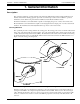
The operational part of the sensing element is the sensing point. The sensing point consists of 3 thermowells (hollow
tubes). Two of the thermowells are welded together. One of the welded thermowells contains a heater and the other
contains a Resistance Temperature Detector (RTD). The third thermowell contains a reference RTD for measuring
the media temperature. There is a delta R (DR) difference between the active and reference RTD resistances. See
Figure 1-1 for the sensing point arrangement.
Figure 1-1. Process Installation Showing the Sensing Point
When the sensing point is in a media that is not flowing (or dry), the media density across the thermowells is low,
causing the active RTD to be at a higher temperature than the reference RTD. In this case, the DR is at its largest
value. When the media starts to flow (or is wet) across the sensing point, the media density across the thermowells
increases, conduction and convection cools the active RTD in proportion to the density of the fluid, and the DR
decreases.
8-66 BASIC
12-64 BASIC