
Installation Owner manual


Doc. No. 06EN003264 Rev. A 2 - 3 Models 12-64/8-66 Basic Switch
CHAPTER 2 - INSTALLATION FLUID COMPONENTS INTL
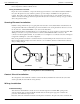
enclosures in the downward direction so condensed moisture that collects in the conduit will not drain into the
enclosure. The local enclosure may be turned not more than 180° using the threads on the sensing element stand
pipe to gain an acceptable orientation. In addition, FCI recommends sealing off the conduit with a potting Y or other
sealing method to prevent moisture from entering the enclosure.
Minimum Wire Size
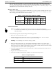
Table 2-1 shows the smallest gauge (maximum AWG number) copper wire used in the electrical cables that connect
the instrument to the customer alarms and to power. Use a lower gauge of wire for less of a voltage drop. Contact
FCI concerning greater distances than those listed in the table.
Table 2-1. Interconnecting Cable Size (AWG)
Cable Connections
Note:
The installation of an AC line switch between the AC power source and the instrument is
recommended. This facilitates easy power disconnection for maintenance, troubleshooting and is an
added safety feature.
Connect the relay output to the customer alarm per the following procedure:
1. Remove the control circuit from it's socket.
2. Install conduit between the local enclosure, the power source and monitoring circuit. Provide watertight
hardware and apply thread sealant to all connections to prevent water damage.
Warning:
Ensure that all power is off before wiring any circuit.
3. When connecting the relay wiring, do so with complete understanding of what the process requires of the
instrument. The instrument has double pole, double throw relay output contacts. See Appendix A, Figure A-2.
For the relay logic, refer to Table 2-2 and in Chapter 3 refer to Figure 3-2. Relay contacts are shown in the relay
de-energized. Wire in accordance with the system requirements.
4. Connect the specified operating power and earth ground to the socket and ground lug. Refer to Figure A-2 for
connection information.
5. Plug the control circuit back into it's socket.
6. Verify proper installation. Ensure that the assemblies are secure and the wiring is correct.
Table 2-2. Relay Energization
Connection
Maximum Distance for AWG
10 ft.
(3m)
50 ft.
(15m)
100 ft.
(31m)
250 ft.
(76m)
500 ft.
152m)
1000 ft.
(305m)
AC Power 22 22 22 20 18 16
Relay (2A) 24 22 20 16 12 10
JUMPER POSITION RELAY STATE
J 12 RELAY DE-ENERGIZED AT NO FLOW / DRY
J13 RELAY DE-ENERGIZED AT FLOW / WET