
Manual

Fluid Components Intl
Document 06EN003327 Rev. - 5 FlexCOR
ä Model CMF Series
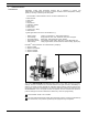
The flow measuring principle is based on the Coriolis law of movement. The flowmeter consists
of a sensor and a transmitter.
Sensor
The sensor is energized by the driver circuit which oscillates the pipe at its resonant frequency.
Two pick-up's, 1 and 2 are placed symmetrically on either side of the driver. If liquid or gas flows
through the sensor, the Coriolis force will act on the measuring pipe and cause a pipe deflection
which can be measured as a phase shift on pick-up 1 and 2.
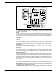
Transmitter
The transmitter consist of a number of function blocks which convert the sensor signals into flow
readings.
Driver circuit
This module excitates the sensor at its resonant frequency. The amplitude of the driver signal is
automatically regulated via a "Phase Locked Loop", to ensure a stable output from the 2 pick-up's.
Power supply
2 different types of power supplies are available. 12 - 24 V a.c./d.c. or a 115 - 230 V a.c. switch
mode type.
Input circuit
The flow proportional signal from the 2 pick-up's is conditioned in this circuit to a digital signal for
further signal processing. The temperature output from the sensor is measured with a current
loop and an optional amplifier in a wheatston configuration. The temperature signal is also
converted into a 32 bit digital format.
Digital signal processor
The signals from the 2 pick-up's, the temperature measurement and the driver frequency is con-
verted into flow proportional signals used for calculation of mass flow, volume flow, fraction flow,
temperature and density. Inaccuracies in the signal converter as a result of long-term drift and
temperature drift are monitored and continously compensated for via the self-monitoring circuit.
The analog to digital conversion takes place in an ultra low noise ASIC with 23 bit signal
resolution. The dynamic range of the signal converter is thus unsurpassed, with a turn down ratio
of min. 3000:1.
CAN communication. The signal converter operates internal via a internal CAN communication
bus. Signals are transferred to/from a signal conditioner to the display module, internal/external
option modules and the dialog module.
Dialog module. The display unit consist of a 3 line display and a 6 key keypad. The display will show
a flowrate or a totalizer value as a primary reading.
The output module converts flow data to an analog, a digital and a relay output. The outputs are
galvanically isolated and can be individually set to suit a particular application.
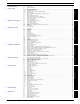
1.1 Mode of operation