
Owner's manual


FLT93 Flow Switch Series FLUID COMPONENTS INTERNATIONAL LLC
Doc. No. 06EN003312 Rev. D 3
This page is subject to proprietary rights statement on last page
Wiring the Instrument
The instrument contains electrostatic discharge
(ESD) sensitive devices. Use standard ESD
precautions when handling the control circuit.
Wiring the Instrument into the Customer Application:
This section describes proper wiring to the transmitter inputs, outputs and interconnection cabling for the optional remote
configuration. See the following table to determine the size of wiring to be used versus the length of the wire.
Alert
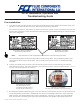
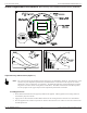
FLT93 Integral (Remote) Wiring Pictorial
FLT93 Integral Wiring Diagram
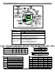
Maximum Distance for AWG
Connection 10 ft. 50 ft. 100 ft. 250 ft. 500 ft. 1000 ft.
(3m) (15m) (31m) (76m) (152m) (305m)
AC Power 222222201816
Relay (6A) 22 16 12 Not Recommended
Flow Element W ires* 22 20 20 18 18 18
*Requires a shielded cable with the shield wire connected to the control socket only.
Only qualified personnel are to wire or test this
instrument. The operator assumes all
responsibilities for safe practices while wiring
or troubleshooting.
SAFETY
GND
HTR 2 REF 3 COM 4 ACT5 HTR 1
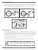
FLT93 Local Wiring Pictorial
SAFETY
GND
COM
ALARM
# 2
N/O
ALARM
# 1
COM
ALARM
# 1
N/C
ALARM
# 1
AC or DC
(+) (-)
N/O
ALARM
# 2
N/C
ALARM
# 2
HTR 7*
ACT 7*
(SHIELD-REMOTE ONLY)*
COM 8*REF 9*HTR 10*
* Connected at Factory,
unless the instrument is
a remote configuration.
PWR PWR
Caution
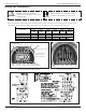
FLT93 Remote Wiring Diagram