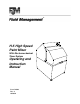
® H-5 High Speed Paint Mixer With Electromechanical Timer System Operating and Instruction Manual Part # 26096 Rev.
CONFIDENTIAL PROPERTY OF FLUID MANAGEMENT® (C) COPYRIGHT 2001 FLUID MANAGEMENT AS AN UNPUBLISHED WORK ALL RIGHTS RESERVED This material cannot be copied or disclosed to others without the prior written permission of Fluid Management. FLUID MANAGEMENT A Unit of IDEX, Corp. 1023 Wheeling Road Wheeling, Illinois 60090-5776 Voice (847) 537-0880 US (800) 462-2466 Fax (847) 537-5530 www.fluidman.
TABLE OF CONTENTS Table Of Contents SAFETY INFORMATION - - - - - - - - - - - - - - - - - - - - - - - - - - - -5 INTRODUCTION- - - - - - - - - - - - - - - - - - - - - - - - - - - - - - - - - -7 INSTALLATION - - - - - - - - - - - - - - - - - - - - - - - - - - - - - - - - - 10 BASIC OPERATION - - - - - - - - - - - - - - - - - - - - - - - - - - - - - - 14 MAINTENANCE PROCEDURES - - - - - - - - - - - - - - - - - - - - - 15 TROUBLE-SHOOTING CHART - - - - - - - - - - - - - - - - - - - - - - 17 SERVICING AND REPAI
Fluid Management ®
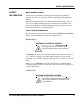
SAFETY INFORMATION SAFETY INFORMATION MIXER WARNING LABELS You should become familiar with important warning labels which are affixed to the mixer, as well as the symbols which appear throughout this manual. Read all warning labels that are on the mixer. Keep them clean so they are easy to read. If the warning labels become damaged or unreadable, new labels can be purchased from Fluid Management. See the parts list in the back of the manual for ordering information.
SAFETY INFORMATION A Caution notice tells you about a danger that could cause injury to you or minor damage to the mixer. When you see a Caution notice in this manual, read it carefully and be sure you understand it before continuing. Information Notice NOTE: If the cabinet vibrates, loosen the locking nuts on the right front leveling foot and slightly adjust the length. An Information notice gives details that will assist you in efficiently using the mixer.
INTRODUCTION INTRODUCTION The Harbil H-5 High Speed Paint Mixer is a basic, automatic mixer designed with concern for safety, reliability and ease of use. It is specifically designed to be placed on the floor. The gear drive assembly requires no lubrication. The belt should last for many years with occasional adjustments. It is a nearly maintenance free device that should deliver many years of reliable service.
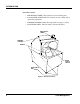
INTRODUCTION General Locations • MECHANICAL TIMER - The twist knob controls mixing time. • DOOR SAFETY SWITCH -The Door must be closed continuously to operate the paint mixer. • WARNING STICKERS - Read these important messages for safety. • ADJUSTABLE FEET - The feet adjust to balence the mixer.
INTRODUCTION Control Panel Push-buttons • POWER SWITCH/TIMER switch for applying power to the machine and setting mix time. • GRADUATION markings for indicating mixing times. Before operating the mixer, carefully read the following important information. WARNINGS • Verify that your paint mixer is properly balanced on the floor. Improper balance may cause severe damage to the machine during the mixing operation. All feet must be adjusted so as to be firmly contacting the floor.
INSTALLATION INSTALLATION UNPACKING AND SETUP INSPECT THE CRATE FOR DAMAGE IMPORTANT: If any damage is found, notify the carrier at once and arrange for inspection in order to claim recovery. Claims for damage must be made by the consignee (YOU). The carrier assumes full responsibility upon acceptance of shipment and will not entertain any claims by the consignor (Fluid Management). REMOVE SHIPPING BLOCKS 1.
INSTALLATION CONNECTING TO THE POWER SOURCE NOTE: The unit must be plugged into a dedicated electrical line with no other equipment using the same circuit. Connect the mixer to a separate, dedicated circuit; for example: 120 volt, 20 ampere. The mixer requires a single, grounded outlet. No other equipment is to be used on this dedicated line. See “Grounded Outlet” on page 13. EXTENSION CORDS Extension cords for 220 VAC models are not recommended.
INSTALLATION GROUNDING This product should be grounded. In the event of an electrical short circuit, grounding reduces the risk of electrical shock by causing the over current protection device to open the electrical circuit. This product is equipped with a cord having a grounding wire with an appropriate grounding plug. The plug must be plugged into an outlet that is properly installed and grounded in accordance with all local codes and ordinances.
INSTALLATION WARNING: After you have plugged the mixer into a dedicated power line and leveled it, inspect to be sure that you have removed the shipping materials inside the mixer.
BASIC OPERATION BASIC OPERATION 1. Open the door. 2. Place a can of paint in the mixer with the bail at the top. 3. Close the door. A safety switch prevents operation of the paint mixer while the door is open. 4. Apply power to the paint mixer turning the control knob clock-wise to the appropriate time setting. 5. Mixer stops automatically when mixing is finished. NOTE: Generally, darker colors require longer mixing times. The timer can be set for a mixing time of between 5 and 120 seconds. 6.
MAINTENANCE PROCEDURES MAINTENANCE PROCEDURES To ensure safe, dependable operation of the paint mixer, follow the maintenance schedule detailed below: AS NEEDED Cleaning: • Clean all accessible inside surfaces with soap and water. • Clean control panel surfaces with soap and water. • Clean all outside cabinet surfaces with soap and water. EVERY 6 MONTHS OR 7500 CYCLES Adjustments: • Adjust belt tension as needed.
MAINTENANCE PROCEDURES Use the table below to record your scheduled maintenance on the mixer. CAUTION: Never lubricate gears, as this could cause slippage if belt is contaminated. Keep belt clean, dry and free of soap and water.
TROUBLE-SHOOTING CHART TROUBLESHOOTING CHART Using the chart below, locate the problem in the first column, then select the probable cause to check and action to take from the next two columns. The problems are arranged from the simplest to the most complex. Where appropriate, refer to the Servicing and Repair section to correct the problem. PROBLEM The paint mixer does not start. Paint mixer will not shut off. CHECK ACTION if mixer attached to power. receptacle for voltage.
TROUBLE-SHOOTING CHART An excessive amount of vibration occurs. if mixer is out of balance. • Balance by adjusting the legs. if adjustable leg is broken or dam- • Replace adjustable leg. if the motor connections. • Tighten motor connections as required. for broken wire motor cabling. • Replace motor cable as needed. for faulty contact block on power • Replace motor cable as needed. aged. The POWER light is on and nothing happens. switch. for problem with the motor. • Replace motor.
SERVICING AND REPAIR SERVICING AND REPAIR GENERAL INFORMATION If you do not feel confident about disassembling the paint mixer or replacing a part, DO NOT ATTEMPT THE PROCEDURE. Should problems or questions arise, contact Customer Service at Fluid Management. Carefully read all of the instructions before you begin. For component identification and location, refer to the Parts Section of this manual.
SERVICING AND REPAIR CHANGING POWER SWITCH Read all of the following instructions. If you have any doubt about performing these procedures, please contact Customer Service at Fluid Management. Turn to the Parts Section of this manual for component identification and location. WARNING: ELECTRICAL HAZARD Always shut off the POWER switch and unplug the mixer before servicing. 1. Unplug the power cord from the electrical outlet. 2.
SERVICING AND REPAIR CHANGING MOTOR Read all of the following instructions. If you have any doubt about performing these procedures, please contact Customer Service at Fluid Management. Turn to the Parts Section of this manual for component identification and location. WARNING: ELECTRICAL HAZARD The mixer must be unplugged before attempting this procedure. There is a chance of electrical shock. 1. Unplug the power cord from the electrical outlet. 2. Close front cover of the machine. 3.
SERVICING AND REPAIR CHANGING OR ADJUSTING V-BELT Read all of the following instructions. If you have any doubt about performing these procedures, please contact Customer Service at Fluid Management. Refer to the Parts Section for component identification and location. 1. Unplug the power cord from the electrical outlet. 2. Close front cover of the machine. 3. Release the two (2) latches as shown and open rear of machine. OPEN LATCHES OPEN Figure 6 Opening Rear of Machine 4.
SERVICING AND REPAIR IDLER PULLEY MOTOR LOCK NUT IDLER ADJUSTMENT BOLT DRIVE BELT MAIN DRIVE PULLEY Figure 7 Belt Adjustment 6. Tension is properly adjusted when approximately five (5) ponds of force deflects belt 1/4". 7. Close back cover of machine and secure with latches. 8. Plug machine into power source and test as required.
PARTS SECTION PARTS SECTION This section is designed to assist you in • Performing service functions and • Identifying parts. All repairs must be performed by qualified service personnel. TERMS: Unless prior arrangements have been made, parts will be shipped UPSCOD. All prices are F.O.B. Wheeling, Illinois, and are subject to change without notice. In all correspondence or phone orders for parts, please state model number and serial number of the Miller Mixer.
EQUIPMENT MAINTENANCE LOG RECORD MODEL NUMBER HERE: _________________________ RECORD SERIAL NUMBER HERE: _________________________ SERVICE DATE DESCRIPTION & PARTS REPLACED (STATE IF UNDER WARRANTY) H-5 Paint Mixer Operating & Instruction Manual SERVICED BY 25
PARTS SECTION SERVICE DATE 26 DESCRIPTION & PARTS REPLACED (STATE IF UNDER WARRANTY) SERVICED BY Fluid Management ®
SPARE PARTS ORDER Fluid Management Parts Order Form Photocopy and use this form to Mail or Fax orders to: Fluid ManagementA unit of IDEX | Phone: 1(800) 462-2466 1023 South Wheeling Road | Fax: 1(847) 537-5530 Wheeling, IL 60090 | | Sold To: Ship To: ________________________ ________________________ ________________________ ________________________ ________________________ ________________________ ________________________ ________________________ P.O.
PARTS SECTION SCREW F0103816 GEAR 25788 SHAFT 16022 SHOLDER SCREW F01130424 GEAR 25789 WEIGHT 16120 SCREW F0104A5B36 NUT F01137 SCREW F0104A4B44 LOCK WASHER 16107 ARM 16096 NUT 16106 SHAFT 25929 PULLEY 16008 BEARING 16105 PIN F0108A09N16 PIN F0115A0816 OPTIONAL SQUARE CAN HOLDER 25936 CAN HOLDER 25723 Figure 8 Transmission Arm Assembly 28 Fluid Management ®
PART NO DESCRIPTION NO REQ 03179 LIMIT SWITCH (NOT SHOWN) 1 16008 DRIVE PULLEY 1 16096 TRANSMISSION ARM (INCLUDES BEARINGS) 1 16105 BEARING 2 16106 NUT 1 16107 LOCK WASHER 1 16120 COUNTER WEIGHT 1 16122 SECONDARY SHAFT 1 19337 TIMER KNOB (NOT SHOWN) 1 24895 TIMER (NOT SHOWN) 1 25723 SQUARE CAN HOLDER (OPTION FOR MIXING QURARE CANS) 1 25788 32 TOOTH BEVELED GEAR 1 25789 64 TOOTH BEVELED GEAR 1 25936 CAN HOLDER 1 25969 1/2 HP, 115 VAC MOTOR (NOT SHOWN) 1 26056
Part No. 26096 Rev. A 10/08/01 Fluid Management 1023 Wheeling Road Wheeling, Illinois 60090-5773 Telephone: (847) 537-0880 1-800-462-2466 Fax (847) 537-5530 www.fluidman.com Part No. 26096 Rev.