
User Guide
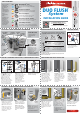
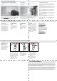

SECTION 6: INSTALLING THE PerforMAX
TM
FILL VALVE
CLIP TO
OVERFLOW
PIPE
OVERFLOW
HOSE
ALIGN
TO
OPENING
Step 27: Disassemble
small parts from red bag
labeled “PerforMAX” Fill
Valve.” Locate the shank
washer and separate the
cone washer from its
center. Press to remove
the cone washer from the
center of the shank
washer as shown above.
Step 28: Place the SHANK
WASHER on the FILL
VALVE SHANK (oriented
with the tapered side
down as shown) and slide
it up to be flush with the
SHANK STOP.
SECTION 7: ADJUSTING THE HEIGHT OF THE PerforMAX
TM
FILL VALVE SECTION 8: INSTALLING AND CONNECTING THE PerforMAX
TM
FILL VALVE
Step 29: Place the FILL
VALVE in the tank to
check height. Do not
attach yet.
Step 30: Check the
height of the PerforMAX
TM
FILL VALVE. It must be 3”
higher than the
OVERFLOW TUBE.
Step 31: Adjust height of
FILL VALVE by turning
lower shank in or out of
valve body. DO NOT
MOVE LOCK RING.
Step 32: Place the
PerforMAX
TM
FILL VALVE in
the tank. Fasten the LOCK
NUT to the FILL VALVE
THREADED SHANK. Hand
tighten. (Do not
overtighten.)
Step 33: Attach the free
end of the black FILL
VALVE REFILL TUBE from
the PerforMAX
TM
FILL
VALVE to the small nipple
on the WATER SAVING
REFILL MODULE. Ensure
the HOSE CLAMP is
secure.
Step 34: Identify your
water supply line by using
steps 36A - 36E to
determine the assembly
parts required to properly
reconnect the water
supply line.
SHANK
WASHER
SHANK
WASHER
PUSH
DOWN
HAND
TIGHTEN
ONLY
ATTACH
FILL
VALVE
REFILL
TUBE
PRESS TO
REMOVE
CONE
WASHER
PerforMAX
TM
Fill Valve
The PerforMAX
TM
Fill Valve maximizes system performance.
It replaces the fill valve currently in your tank.
Locking
Ring
Fill Valve
Refill Tube
Roller
Clamp
Tube
Clamp
Tube
Clamp
Adjustment
Screw
Fill Valve
Float
Fill Valve
Shank
Lock Nut
Coupling Nut
3”
Step 19: Attach the
OVERFLOW HOSE to the top of
the OVERFLOW PIPE via the black
plastic OVERFLOW HOSE CLIP.
Ensure that the opening of the
OVERFLOW HOSE is directly
aligned with the opening of the
OVERFLOW PIPE.
Note: Keep end of hose above
overflow pipe. If hose is
positioned down into overflow
pipe, it will siphon water to bowl.
Shank &
Cone
Washer
Coupling
Nut
Refill
Clip
Locknut
Roller &
Tube Clamp
Fill Valve
Refill Tube
INCLUDES ASSEMBLY PARTS
SHANK
WASHER
SLIDE UP
TO HERE
DO NOT
MOVE
LOCK
RING
PROCEED TO FOLLOWING
PAGE FOR NEXT STEPS
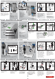
SECTION 4: INSTALLING THE DUO FLUSH
TM
VALVE
Step 14: Remove foam
around ADJUSTMENT DIALS.
Step 15: Locate white arrow
on SNAP-ON MOUNT and align
it facing the OVERFLOW PIPE.
Do not install yet.
FLUSH
CABLE
SEE NOTE
BELOW
Step 18: Press DUO FLUSH
onto seat.
Note: Be sure the FLUSH
CABLE is not caught
between the SNAP-ON
MOUNT and the FLUSH
VALVE SEAT when
installing.
ALIGNMENT
ARROW
FLUSH
VALVE SEAT
FLUSH VALVE
SNAP-ON
MOUNT
FLUSH
CABLE
INSTALLING THE DUO FLUSH VALVE
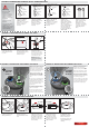
SECTION 5: INSTALLING THE DUAL ACTION HANDLE
THE FLUSH HANDLE
ACTUATOR SHOULD
BE ORIENTED
VERTICALLY
THE FLUSH HANDLE SHOULD BE
MOUNTED HORIZONTALLY
HOLD HANDLE HORIZONTALLY
REMOVE LOCK NUT
TURN LOCK NUT
CLOCKWISE
TO LOOSEN
ORIENT TABS
VERTICALLY
Step 24: Install nut
counter-clockwise to
tighten.
Step 20: Remove the
HANDLE from the green
bag labeled D.
Step 21: Unthread LOCK
NUT in a clockwise
rotation on HANDLE.
Step 22: Rotate handle
COLLAR so alignment
tabs are positioned
vertically.
Step 23: Insert the HANDLE
into toilet hole.
Step 25: Ensure that the
HANDLE is positioned horizon-
tally by holding handle horizon-
tally before snapping into place
into tank.
Alignment
Tabs
Dual Action
Handle
Collar
Lock Nut
(Turn counterclockwise
to tighten)
Handle
Actuator
Flush
Cable
Step 26: Attach
HANDLE ACTUATOR to
the handle COLLAR on
HANDLE. If necessary,
rotate DUO FLUSH
TM
on
SNAP-ON MOUNT so the
FLUSH CABLE angles
toward the tank lever
hole.
F
U
L
L
Step 16: Unsnap FLUSH
CABLE from DUO FLUSH
TM
.
Note: Make sure not to
sharply bend or kink the
FLUSH CABLE.
TANK LEVER
HOLE
Step 17: Rotate
DUO FLUSH
TM
on
SNAP-ON MOUNT so
the FLUSH CABLE
points directly
toward the tank
lever hole.
FLUSH
CABLE
FLUSH
CABLE
SNAP-ON
MOUNT