
Install Instructions

®
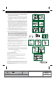
STEP 2
COUPLING
NUT
SHANK AND
CONE WASHER
(SEE STEP 4)
LOCK NUT
ANGLE
ADAPTER
STEP 3
LOCK
NUT
CONE
WASHER
COUPLING
NUT
WATER
SHUTOFF
LOCK
NUT
EXISTING
WASHER
EXISTING
COUPLING
NUT
WATER
SHUTOFF
DO NOT use
plumber's putty
to seal these
fittings.
These parts must be
used as illustrated to
insure water-tight
connection. Use of
existing COUPLING NUT
or CONE WASHER may
result in water leakage.
Water supply tube or pipe must extend at least
1/2" inside THREADED SHANK of VALVE
(does not apply to flanged tubing).
CAUTION: DO NOT USE CONE WASHER
WITH PLASTIC SUPPLY LINE.
CAUTION: Overtightening of LOCK NUT or COUPLING
NUT could result in breakage and potential flooding.
METAL/COPPER METAL FLANGED METAL SPIRAL VINYL/BRAIDED
FLARED TUBING TUBING TUBING CONNECTOR
Use existing
COUPLING NUT
and WASHER.
Captive CONE WASHERS
already included. No
additional washers needed.
Use existing spiral CONE WASHER.
Fluidmaster CONE WASHER may not
seal completely on spiral type supply line.
STEP 8
CONE
WASHER
SHANK
SHANK
WASHER
THREADED SHANK
TANK
BOTTOM
SHANK
WASHER
STEP 4
DO NOT
MOVE
LOCK RING
STEP 6
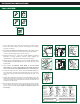
STEP 1
MEASURE
HEIGHT ONLY; DO
NOT INSTALL
1"
"C.L."
MARK
STEP 5
HAND-
TIGHTEN
ONLY
PUSH
DOWN
STEP 7
LOCK
NUT
EXISTING
CONE
WASHER
COUPLING
NUT
WATER
SHUTOFF
LOCK
NUT
COUPLING
NUT
WATER
SHUTOFF
DO NOT USE:
INSTALLATION INSTRUCTIONS
:DEDEEN SLOOT
1. Shut off water supply to tank. Flush tank and sponge out remaining water.
Remove old fill valve assembly, tank ball, and wire guide unit (or flapper),
using pliers if necessary.
2. If you have a Fluidmaster bowl cleaning system, carefully disconnect the
tube from the FILL VALVE. Do not disconnect the tube from the dispenser
(if you don’t have a cleaning system, continue to Step 3).
3. Disassemble small parts – LOCK NUT, SHANK WASH
ER and ANGLE
ADAPTER for VALVE installation (required); CONE WASHER and
COUPLING NUT for water supply connection (optional–see Step 8).
4. Carefully remove CONE WASHER from center of SHANK WASHER. Place
SHANK WASHER on THREADED SHANK of new VALVE. Place flat surface
against VALVE.
5. When installed, the CRITICAL LEVEL MARK on the FILL VALVE
(identified by a C.L. mark on the Fluidmaster FILL VALVE) should be at
least 1" above the top of the OVERFLOW PIPE. This
is a plumbing code.
6. To adjust the height of the FILL VALVE, twist the THREADED SHANK in or
out of VALVE body. The height of the VALVE adjusts from 9 to 14 inches. On
some models, a clicking noise will be heard when adjusting the height. This is
normal.
7. Position VALVE inside tank. Push down on the VALVE SHANK (not the TOP)
while tightening LOCK NUT. Hand-tighten only. DO NOT OVERTIGHTEN or
tank may crack. Make sure FLOAT CUP does not touch toilet tank
walls, trip
mechanism or FLUSH VALVE.
8. Before continuing, determine the type of water supply connection you have
from the chart on the left and use the appropriate assembly parts required to
properly reconnect the water supply. DO NOT use plumber’s putty to seal
these fittings.