
User manual


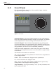
Table Of Contents
- Table of Contents
- 1 Before You Start 1
- 2 Introduction 7
- 3 Specifications and Environment Conditions 9
- 4 Quick Start 13
- 5 Parts and Controls 15
- 6 General Operation 17
- 7 Controller Operation 19
- 7.1 Target Temperature 19
- 7.2 Temperature Set-point 19
- 7.3 Temperature Scale Units 21
- 7.4 Scan 22
- 7.5 Set-point Resistance 23
- 7.6 Temperature Scale Units 23
- 7.7 Secondary Menu 23
- 7.8 Heater Power 23
- 7.9 Proportional Band 24
- 7.10 Controller Configuration 25
- 7.11 Operating Parameters 25
- 7.12 Serial Interface Parameters 26
- 7.13 Calibration Parameters 27
- 8 Digital Communication Interface 29
- 9 Calibration Procedure 35
- 10 Maintenance 39
- 11 Troubleshooting 41
- Figures
- Tables

5 Parts and Controls
5.1 Back Panel
The back panel (Figure 2) consists of the power inlet, power switch, serial
port, and fan.
Power Inlet – At the rear of the calibrator is the removable power cord in
let that plugs into an IEC grounded socket.
Power Switch – The power switch is located on the power entry module
(PEM).ThePEMalsohousesthefuses.ThePEMallowstheunittobefield
switchable for 115 VAC (±10%) or 230 VAC( ±10%) operation. (See Section
6.2, Switching to 230 V Operation.)
Serial Port – A DB-9 male connector is present for interfacing the calibrator
to a computer or terminal with serial RS-232 communications.
Fan – The fan inside the calibrator varies in speed. As the target tempera
-
ture increases the fan speed decreases. Slots are provided for airflow. The
area around the calibrator must be kept clear to allow adequate ventilation.
The airflow is directed out the two sides.
15
5
Parts and Controls
RS-232
115V - 3AT 250V
230V - 1.6AT 250V
115 VAC 50/60 Hz 3A
230 VAC 50/60 Hz 1.6A
~
Figure 2 Back Panel