
User Manual
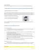
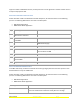
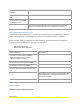

Table Of Contents
- Table of Contents
- Introduction
- Comprehensive Integration Instructions for Fluke FBLE radio module
- Interface to external Microprocessor
- Physical Interface
- Software Interface
- Network Command Communication
- Device Command Communication
- Device Notification Communication
- SPI Data Packets
- SPI Packet Formats
- SPI Packet Field Definitions
- SPI Packets are Big-Endian
- Network Control Commands
- Network Control Commands
- Device Control Command Payloads
- Device Control Command Responses
- Interrupt Status Word
- Network Control Commands and Responses are Big-Endian
- BLE Custom UUID
- Firmware Upgrade over BLE
- External processor upgrade over BLE

Fluke Corporation Telephone Facsimile Email
PO Box 9090 Everett WA 98206.9090 USA 425.347.6100 425.356.5108 http//www.fluke.com
Introduction
This document is intended to allow developers to work with the CC2540 based BLE Slave Module.
Comprehensive Integration Instructions for Fluke FBLE radio module
LABELING REQUIREMENTS FOR END-PRODUCT
The Original Equipment Manufacturer (OEM) must ensure that FCC labeling requirements are met. The
FBLE module is labeled with its own FCC ID and IC Certification Number. The FCC ID and IC certification
numbers are not visible when the module is installed inside another device. The final end product must
be labeled in a visible area with the following:
“Contains Transmitter Module FCC ID: T68-FBLE”
“Contains Transmitter Module IC: 6627A-FBLE”
The Fluke FBLE Module has been certified with its own on-board antenna and must not be used with
other antenna(s).
Interface to external Microprocessor
Physical Interface
The CC254x based Slave module uses a modified SPI interface to communicate as a SPI Slave
device. The Interface needs to be configured as described below.
• The SPI interface is implemented in the 4-wire configuration consisting of signals RFEN (i.e., chip
select line), SIMO, SOMI and SCK.
• The BUSY line must go low before the master begins to clock data. The BUSY line must be
checked between each byte transaction as well.
• A Interrupt line is provided to allow the radio to notify the SPI master when there is data
pending. The line is level triggered. When the line is high, the Interrupt Status word should be
read. When the line is low, no data is pending.
• SPI port speed is controlled by the master or slave application up to a maximum speed of 4
MHz.
• Positive clock polarity, non-delayed clock phase, MSB sent first.
Software Interface
The BLE Radio uses a propriety packet format. This format allows the radio to be configured via
network control commands, and allows data to be passed via device control commands. In order to