DSX-600 Series CableAnalyzer™ Users Manual Software Version 6.3 July 2019 ©2019 Fluke Corporation All product names are trademarks of their respective companies.
LIMITED WARRANTY AND LIMITATION OF LIABILITY Each Fluke Networks product is warranted to be free from defects in material and workmanship under normal use and service unless stated otherwise herein. The warranty period for the mainframe is one year and begins on the date of purchase. Parts, accessories, product repairs and services are warranted for 90 days, unless otherwise stated. Ni-Cad, Ni-MH and Li-Ion batteries, cables or other peripherals are all considered parts or accessories.
Contents Chapter 1 Get Acquainted Overview of Features ......................................................1 Contact Fluke Networks .................................................2 Register Your Product ....................................................2 Technical Reference Handbook .....................................2 Additional Resources ......................................................2 Supplements and Updated Manuals .............................3 Kit Contents .............................
DSX-600 Series CableAnalyzer Users Manual Chapter 2 Certify Twisted Pair Cabling The DSX-600 Series CableAnalyzer Home Screen ......... 25 Make Sure Your Tester is Ready to Certify Cabling ............................................................................ 28 Set the Reference ........................................................... 29 Settings for Twisted Pair Tests ....................................... 31 How to Do an Autotest ..................................................
Contents Delete, Rename, and Move Results ............................... 72 Manage Results on a Flash Drive ................................... 74 Upload Results to a PC ................................................... 75 View the Memory Status ................................................ 76 Chapter 5 Use Projects Why Use Projects? .......................................................... 77 Set Up a Project .............................................................. 78 The PROJECT Screen ....
DSX-600 Series CableAnalyzer Users Manual Sign In to LinkWare Live from a Desktop or Mobile Device ................................................................. 96 Import Projects from LinkWare Live into LinkWare PC .................................................................................... 97 Learn More About LinkWare Live ................................. 97 Chapter 7 Maintenance Verify Operation ............................................................ 100 Clean the Tester ............
List of Figures Figure Page 1. Main Tester Connectors, Keys, and LEDs (DSX-602 shown) .......8 2. Remote Tester Connectors, Keys, and LEDs (DSX-602 shown) ...........................................................................................10 3. How to Attach and Remove Link Interface Adapters.................12 4. How to Prevent Damage to the Permanent Link Adapter Cables (Model DSX-600-PRO or DSX-602-PRO or optional) ...................13 5. LEDs Show the Remote’s Battery Status.......
DSX-600 Series CableAnalyzer Users Manual 22. Reference Connections for Tests on Coaxial Cabling................. 56 23. Equipment for Tests on Coaxial Cabling..................................... 59 24. Examples of Connections for Tests on Coaxial Cabling ............. 61 25. Autotest Results for Coaxial Cabling .......................................... 62 26. Connections for Coaxial Tests Without a Remote...................... 66 27. RESULTS Screen ............................................
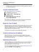
Chapter 1: Get Acquainted Overview of Features The DSX-600 and DSX-602 CableAnalyzer™ main and remote units are rugged, hand-held testers that let you certify, troubleshoot, and document copper network cabling. The DSX-600/602 include these features: Note Feature descriptions in the DSX-600 Series documentation apply to DSX-600 and DSX-602 testers unless stated otherwise. The testers certify twisted pair cabling to Cat 6A/Class EA limits (500 MHz) in less than 10 seconds.
DSX-600 Series CableAnalyzer Users Manual LinkWare Stats software makes browsable, graphical reports of cable test statistics. Contact Fluke Networks www.flukenetworks.com/support info@flukenetworks.com 1-800-283-5853, +1-425-446-5500 Fluke Networks 6920 Seaway Boulevard, MS 143F Everett WA 98203 USA Fluke Networks operates in more than 50 countries worldwide. For more contact information, go to our website.
Chapter 1: Get Acquainted Supplements and Updated Manuals Supplements and Updated Manuals If necessary, Fluke Networks will put a supplement for this manual, or an updated manual, on the Fluke Networks website. To see if a supplement or updated manual is available, log on to www.flukenetworks.com, click SUPPORT > Manuals, then select a product.
DSX-600 Series CableAnalyzer Users Manual Table 1. Symbols ~ This product complies with the WEEE Directive marking requirements. The affixed label indicates that you must not discard this electrical/electronic product in domestic household waste. Product Category: With reference to the equipment types in the WEEE Directive Annex I, this product is classed as category 9 "Monitoring and Control Instrumentation" product. Do not dispose of this product as unsorted municipal waste.
Chapter 1: Get Acquainted WSafety Information WSafety Information WWarningX To prevent possible fire, electric shock, or personal injury: Read all safety information before you use the Product. Carefully read all instructions. Do not open the case. You cannot repair or replace parts in the case. Do not modify the Product. Use only replacement parts that are approved by Fluke Networks. Do not touch voltages > 30 V AC rms, 42 V AC peak, or 60 V DC.
DSX-600 Series CableAnalyzer Users Manual 6 Remove the input signals before you clean the Product. Do not put metal objects into connectors. Batteries contain hazardous chemicals that can cause burns or explode. If exposure to chemicals occurs, clean with water and get medical aid. Remove the batteries if the Product is not used for an extended period of time, or if stored in temperatures above 50 °C. If the batteries are not removed, battery leakage can damage the Product.
Chapter 1: Get Acquainted WSafety Information Use only AC adapters approved by Fluke Networks for use with the Product to supply power to the Product and charge the battery. WCaution To prevent damage to the tester or cables under test, to prevent data loss, and to make sure your test results are as accurate as possible: Do not connect the tester to an active network. Doing so causes unreliable test results, can disrupt network operations, and can cause damage to the tester.
DSX-600 Series CableAnalyzer Users Manual Connectors, Keys, and LEDs BK88.EPS Figure 1. Main Tester Connectors, Keys, and LEDs (DSX-602 shown) Connector for a link interface adapter LCD display with touchscreen : Starts a test. Turns on the tone generator if a remote tester is not connected to the main tester. To start a test, you can also tap TEST on the display.
Chapter 1: Get Acquainted Connectors, Keys, and LEDs : Press to go to the home screen. Connector for the AC adapter. The LED is red when the battery charges, and green when the battery is fully charged. The LED is yellow if the battery will not charge. See “Charge the Battery” on page 14. RJ45 connector: Lets you connect to a network for access to Fluke Networks cloud services.
DSX-600 Series CableAnalyzer Users Manual A B G H C D F E BK42.EPS Figure 2. Remote Tester Connectors, Keys, and LEDs (DSX-602 shown) Connector for a link interface adapter PASS LED comes on when a test passes. TEST LED comes on during a test. FAIL LED comes on when a test fails. TALK LED comes on when the talk function is on (). The LED flashes until the main tester accepts the request to talk.
Chapter 1: Get Acquainted Connectors, Keys, and LEDs TONE LED flashes and the tone generator comes on if you press when a main tester is not connected to the remote. LOW BATTERY LED comes on when the battery is low. The LEDs also have these functions: Battery gauge (see Figure 5 on page 15) Volume indicator for the TALK function Progress indicator for software updates : Starts a test. Turns on the tone generator if a main tester is not connected to the remote.
DSX-600 Series CableAnalyzer Users Manual About Link Interface Adapters Link interface adapters let you connect the DSX CableAnalyzer to different types of twisted pair links. Figure 3 shows how to attach and remove adapters. WCaution To prevent damage to the cables on the permanent link adapters and to make sure your test results are as accurate as possible, do not twist, pull on, pinch, crush, or make kinks in the cables. See Figure 4 on page 13. BK109.EPS Figure 3.
Chapter 1: Get Acquainted About Link Interface Adapters 5 in (13 cm) minimum GPU108.EPS Figure 4.
DSX-600 Series CableAnalyzer Users Manual AC Adapter and Battery You can use the AC adapter (model PWR-SPLY-30W) or the lithium ion battery (model VERSIV-BATTERY) to supply power to the tester. To remove the battery, see “Remove the Battery” on page 106. Charge the Battery Before you use the battery for the first time, charge the battery for about 2 hours with the tester turned off. To charge the battery Connect the AC adapter to the 15V jack on the left side of the tester.
Chapter 1: Get Acquainted AC Adapter and Battery Check the Battery Status On a main tester The battery status icon is in the upper-left corner of the screen: Battery is full. Battery is approximately half full. If the AC adapter is not connected, the red bar shows that the battery is very low. Connect the AC adapter to charge the battery and make sure the tester continues to operate. The red bar also shows if the AC adapter is connected, but the battery is not installed.
DSX-600 Series CableAnalyzer Users Manual To see more information about a remote’s battery status 1 Make the connections shown in Figure 6 and turn on both testers. 2 Make sure the connection icon shows at the top of the screen ( 3 ). Tap TOOLS, then tap Battery Status. When the AC adapter is not connected, the screen shows the Time Remaining, which is the approximate battery life at the present rate of use. Verify Operation The tester does a self test when you turn it on.
Chapter 1: Get Acquainted Verify Operation DSX CableAnalyzer with two channel adapters and a patch cord DSX CableAnalyzer with permanent link* and channel adapters * Model DSX-600-PRO/DSX-602-PRO or optional BK148.EPS Figure 6.
DSX-600 Series CableAnalyzer Users Manual How to Use the Touchscreen The DSX CableAnalyzer main unit’s Taptive™ user interface lets you use a touchscreen to control the tester. You can operate the touchscreen with your fingertip or with a stylus that is made for projected capacitance touchscreens. WCaution For correct operation and to prevent damage to the touchscreen: Touch the screen only with your fingers or with a stylus that is made for projected capacitance touchscreens.
Chapter 1: Get Acquainted How to Use the Touchscreen To zoom in, use the reversepinch gesture To move the image, drag it in any direction. To zoom out, use the pinch gesture To quickly go back to 1:1 magnification, double-tap the screen. BA45.EPS Figure 7.
DSX-600 Series CableAnalyzer Users Manual Change the Language On the home screen, tap the TOOLS icon, tap Language, then tap a language. Buttons to Do Tests and Save Results When a test is completed and more than one button shows at the bottom of the screen, the tester highlights one in yellow to recommend which one to tap. Figure 8 shows the buttons you will see. Note To change the Auto Save setting, tap the Next ID panel on the home screen. A B C D E F G BK40.EPS Figure 8.
Chapter 1: Get Acquainted Buttons to Do Tests and Save Results SAVE (yellow), TEST (gray): These buttons show if the test passed and Auto Save is off. When you tap SAVE, you can save the results with an ID that you make or select. When you tap TEST, you can select to save the results or do the test again and not save the results. UNSAVED RESULT: This button shows if Auto Save is off and you go to the home screen when a test is completed. Tap this button to see the result.
DSX-600 Series CableAnalyzer Users Manual Overview of Memory Functions You can save approximately 12,700 Cat 6A Autotest results, with plot data included, in the DSX-600 Series main tester. The capacity available for test results depends on the space used by the software and custom test limits in the tester. To see the memory status On the home screen, tap the TOOLS icon, then tap Memory Status.
Chapter 1: Get Acquainted About LinkWare Applications If the test failed before, and you saved the results, you can select it on the RESULTS screen, then press TEST AGAIN to replace the results for that ID. Notes Cable IDs are case-sensitive. For example, the tester saves result with the names “A0” and “a0” in two different records. A cable ID can have a maximum of 60 characters. If you delete all the ID sets in a project, the tester makes a default set that starts with 001.
DSX-600 Series CableAnalyzer Users Manual LinkWare Stats The LinkWare Stats Statistical Report software that is included with LinkWare PC software provides statistical analysis of cable test reports and generates browsable, graphical reports. For instructions about LinkWare PC and LinkWare Stats software, see the guides for getting started and the online help available under Help on the LinkWare PC and LinkWare Stats menus.
Chapter 2: Certify Twisted Pair Cabling WWarningX Before you use the DSX CableAnalyzer, read the safety information that starts on page 3. The DSX-600 Series CableAnalyzer Home Screen The home screen (Figure 9) shows important test settings. Before you do a test, make sure these settings are correct.
DSX-600 Series CableAnalyzer Users Manual LM N A B C K D E F G H I J BK110.EPS Figure 9. The Home Screen PROJECT: The project contains the settings for a job and helps you monitor the status of a job. When you save test results, the tester puts them in the project. Tap the PROJECT panel to edit the project settings, select a different project, or make a new project. Shows a summary of the test results in the project: : The number of tests that passed.
Chapter 2: Certify Twisted Pair Cabling The DSX-600 Series CableAnalyzer Home Screen : The number of tests that failed. : The number of tests with an overall marginal result. The test setup panel shows the settings the tester will use when you tap TEST or press . To change these settings, tap the panel. Icons show the status of the Store Plot Data and AC Wire Map settings. See Table 2 on page 33. Next ID: The Next ID panel shows the ID that the tester gives to the next test results you save.
DSX-600 Series CableAnalyzer Users Manual % Tested does not show if your project contains only a Next ID list. See “About Next ID Sets” on page 83 for more information about the Next ID list. This icon shows when the tester’s link interface adapter is connected to the adapter on a remote and the remote is turned on. The asset management icon shows when the owner of a LinkWare Live account has enabled the asset management service on the tester. See “About the Asset Management Service” on page 93.
Chapter 2: Certify Twisted Pair Cabling Set the Reference Make sure you select the correct test limit for the job. See Table 2 on page 32. Make sure the cords and connectors for all test equipment and patch cords are in good condition. Make sure the battery is fully charged. Send the testers to a Fluke Networks service center every 12 months for factory calibration.
DSX-600 Series CableAnalyzer Users Manual Channel adapters 6 inch (15 cm) reference patch cord Permanent link adapter* Channel adapter * Model DSX-600-PRO or DSX-602-PRO or optional BK89.EPS Figure 10.
Chapter 2: Certify Twisted Pair Cabling Settings for Twisted Pair Tests Settings for Twisted Pair Tests Table 2 gives descriptions of the settings for twisted pair tests. To set up a project, which includes the settings in Table 2, cable IDs, and operator names, see Chapter 5. To set up a twisted pair test 1 On the home screen, tap the test setup panel. 2 On the CHANGE TEST screen, select a twisted pair test to change, then tap EDIT. Or to set up a new twisted pair test, tap NEW TEST.
DSX-600 Series CableAnalyzer Users Manual Table 2. Settings for Twisted Pair Tests Setting Description Cable Type Select a cable type that is correct for the type you will test. To see a different group of cable types, tap MORE, then tap a group. To make a custom cable type, tap Custom in the Cable Groups list. NVP Nominal velocity of propagation. The tester uses the NVP and the propagation delay to calculate the length of the cable.
Chapter 2: Certify Twisted Pair Cabling Settings for Twisted Pair Tests Table 2. Settings for Twisted Pair Tests (continued) Setting Description Store Plot Data Off : The tester does not save plot data for frequencydomain tests or for the HDTDR/HDTDX analyzers. You can see the plots before you save the test and exit the results screen. The saved results show frequency-domain measurements in a table and do not include the HDTDR/ HDTDX plots.
DSX-600 Series CableAnalyzer Users Manual Table 2. Settings for Twisted Pair Tests (continued) Setting AC Wire Map Description The AC Wire Map test lets you do tests on links connected through midspan PoE (Power over Ethernet) devices. See the Technical Reference Handbook. When the AC Wire Map test is on, this icon shows on the home screen: Notes Always turn off the AC wire map test when you will not do tests through a PoE device. The AC wire map test increases the time for an Autotest.
Chapter 2: Certify Twisted Pair Cabling Settings for Twisted Pair Tests T568A T568B Crossover 1000BASE-T Crossover Rollover 2 x Two-Pair Crossed Ethernet Two-Pair Ethernet Two-Pair Crossed CSU/DSU USOC Two-Pair Token Ring USOC Single-Pair ATM/TP-PMD Straight ATM/TP-PMD Crossed One Pair (1,2) GPU85.EPS Figure 11.
DSX-600 Series CableAnalyzer Users Manual M12-D Two-Pair M12-D Two-Pair Crossed M12 X-Code ix Industrial™ Ethernet 6 7 4 5 9 10 4 5 GPU238.EPS Figure 12.
Chapter 2: Certify Twisted Pair Cabling How to Do an Autotest How to Do an Autotest When you tap TEST on the main tester or press on the main or remote tester, the testers do an Autotest. The Autotest includes all the tests necessary to certify that the cabling meets or exceeds the performance requirements specified in the selected test limit. Figure 13 shows the equipment for Autotests on twisted pair cable. C A B D BK111.
DSX-600 Series CableAnalyzer Users Manual To do an Autotest on twisted pair cable 1 Attach permanent link or channel adapters to the main and remote testers. 2 Make sure that the home screen shows the correct settings for the job. To make sure that other settings are correct, tap the test setup panel, make sure the correct test is selected on the CHANGE TEST SCREEN, then tap EDIT to see more settings. Table 2 on page 32 describes the settings.
Chapter 2: Certify Twisted Pair Cabling How to Do an Autotest Horizontal cabling Optional consolidation point Patch panel Wall outlet Start permanent link Tester with permanent link adapter* End permanent link Remote with permanent link adapter* * Permanent link adapters: Model DSX-600-PRO or DSX-602-PRO or optional BK97.EPS Figure 14.
DSX-600 Series CableAnalyzer Users Manual Horizontal cabling Hub or switch Patch cord from hub or switch Optional consolidation point Wall outlet Patch panels Start channel Tester with channel adapter Patch cord from PC End channel Remote with channel adapter BK96.EPS Figure 15. Channel Connections “Bad Patch Cord” Message To comply with standards for tests on channels, the tester removes the effects of the channel adapters and their connections from the test results.
Chapter 2: Certify Twisted Pair Cabling Twisted Pair Autotest Results Twisted Pair Autotest Results The tests listed below apply to twisted pair cabling. Note Some tests are not included in some test limits.
DSX-600 Series CableAnalyzer Users Manual PASS*/FAIL* Results A result shows an asterisk when measurements are in the tester’s accuracy uncertainty range (Figure 16) and the asterisk is required by the selected test limit. These results are marginal. A PASS* shows that the cable’s performance is satisfactory. If a cable must get a PASS result to agree with your requirements for quality, identify and correct the problems with the cable and do the Autotest again.
Chapter 2: Certify Twisted Pair Cabling Twisted Pair Autotest Results WIRE MAP Tab The WIRE MAP tab shows the connections between the ends of the cable under test. The tester compares the connections to the selected Outlet Configuration to get a PASS or FAIL result. If the wire map test fails, you can continue or stop the Autotest. Or, you can tap SCAN ON to do the wire map test continuously while you look for the fault. To continue the Autotest after you correct the fault, tap SCAN OFF, then tap CONTINUE.
DSX-600 Series CableAnalyzer Users Manual D E A B C F Figure 17. WIRE MAP Tab BA59.EPS The name of the outlet configuration used for the test. The outlet configuration is a setting on the TEST SETUP screen. The wire map of the cabling. The main tester is at the left side of the wire map. Tap to see information about wire map faults. If shows, tap it to see a message about the results, such as Bad patch cord at remote. The overall result for the Autotest.
Chapter 2: Certify Twisted Pair Cabling Twisted Pair Autotest Results The result for the wire map test: The wire map does not agree with the outlet configuration selected for the test. The wire map agrees with the outlet configuration selected for the test. When more than one button shows at the bottom of the screen, the tester highlights one in yellow to recommend which one to tap. See “Buttons to Do Tests and Save Results” on page 20.
DSX-600 Series CableAnalyzer Users Manual PERFORMANCE Tab The PERFORMANCE tab (Figure 18) shows the overall result for each test that is required by the selected test limit. C A B D E BA86.EPS Figure 18. PERFORMANCE Tab The test limit and cable type used for the test. To see all the settings used for the test, tap the panel. To see detailed results for a test, tap the panel. The overall result for the Autotest. If the result shows an asterisk, See “PASS*/FAIL* Results” on page 42.
Chapter 2: Certify Twisted Pair Cabling Twisted Pair Autotest Results The results are within the limit. The selected test limit does not have a limit for the test, or a dB rule applies. See the Technical Reference Handbook. The results are within the range of accuracy uncertainty for the tester. See “PASS*/FAIL* Results” on page 42. The measurement shown for frequency-domain results is the worst margin. (The insertion loss plot is different. See the Technical Reference Handbook.
DSX-600 Series CableAnalyzer Users Manual A I B H C D E F G BA104.EPS Figure 19. Tabular Results Screen for a Frequency-Domain Test The location where the tester made the measurements. To switch between results for the main and remote, tap REMOTE or MAIN (). The results are for the wire pair or pairs shown. To see the results for a different pair or pairs, tap a tab on the right side of the screen ().
Chapter 2: Certify Twisted Pair Cabling Twisted Pair Autotest Results The measured value. The limit specified by the selected test limit. MARGIN is the difference between the measured value and the limit. The value is in a red box if the measurement exceeds the limit. To switch between results for the main unit and the remote, tap REMOTE or MAIN. To see the results for a different pair or pairs, tap a tab. The result for the pair.
DSX-600 Series CableAnalyzer Users Manual A M B C D E L K F G HI J BA71.EPS Figure 20. Plot Screen for a Frequency-Domain Test The location of the measurements. To switch between results for the main and remote, tap REMOTE or MAIN (). Measured values for the wire pairs. The limit line (in red) for the measurement. Note If the limit line is black, the tester does not evaluate the measurement at those frequencies because a dB rule applies. See the Technical Reference Handbook.
Chapter 2: Certify Twisted Pair Cabling Twisted Pair Autotest Results The vertical scale is the measured value in decibels. The horizontal scale is the frequency range in megahertz. To see help for the screen, tap . To switch between results for the main unit and the remote, tap REMOTE or MAIN. The margin at the cursor’s location. The margin is the difference between the measured value and the limit. The margin is negative if the pair failed. The measured value at the cursor’s location.
DSX-600 Series CableAnalyzer Users Manual DIAGNOSTIC Tab If an Autotest on twisted pair cabling fails or has marginal results, the DSX-600/602 CableAnalyzer automatically gives you HDTDR and HDTDX plots to help you find faults. To see the plots, tap the DIAGNOSTIC tab, then tap the HDTDR or HDTDX panel (Figure 21). To get only diagnostics results, select Diagnostics from the TOOLS menu. These results do not include a PASS/FAIL status.
Chapter 2: Certify Twisted Pair Cabling Twisted Pair Autotest Results Continuous Tests To do the wire map, length, or resistance test continuously, go to the home screen, tap TOOLS > Single Tests, then tap a test. The wire map test compares the results to the outlet configuration specified by the selected test limit and shows the connections agree or if they do not. if The length and resistance tests do not compare the results to a test limit. To save the result, tap SCAN OFF > SAVE.
DSX-600 Series CableAnalyzer Users Manual 54
Chapter 3: Certify Coaxial Cabling The optional DSX-CHA003 coaxial adapters let you use the DSX CableAnalyzer to certify coaxial cabling for network and video applications. Set the Reference for Coaxial Tests To use DSX-CHA003 adapters, you must set the reference for coaxial tests. The reference procedure sets a baseline for insertion loss and resistance measurements. Set the reference at these times: Every 30 days, at minimum. To ensure maximum accuracy of test results, set the reference daily.
DSX-600 Series CableAnalyzer Users Manual Notes Set the reference only after the testers are at an ambient temperature between 10 °C and 40 °C (50 °F and 104 °F). The tester will not let you set the reference if the patch cord is longer than 30 cm (12 in). You can also set the reference with a 50 patch cord 3 On the home screen, select a coaxial cable test. 4 On the home screen, tap TOOLS, then tap Set Reference. 5 On the SET REFERENCE screen tap TEST.
Chapter 3: Certify Coaxial Cabling Settings for Coaxial Tests Settings for Coaxial Tests Table 3 gives descriptions of the settings for coaxial tests. To set up a project, which includes the settings in Table 3, cable IDs, and operator names, see Chapter 5. To set up a coaxial test 1 On the home screen, tap the test setup panel. 2 On the CHANGE TEST screen, select a coaxial test to change, then tap EDIT. Or to set up a new coaxial test, tap NEW TEST.
DSX-600 Series CableAnalyzer Users Manual Table 3. Settings for Coaxial Tests Setting Description Cable Type Select a cable type that is correct for the type you will test. To see a different group of cable types, tap MORE, then tap a group. To make a custom cable type, tap Custom in the Cable Groups list. NVP Nominal velocity of propagation. The tester uses the NVP and the propagation delay to calculate the length of the cable.
Chapter 3: Certify Coaxial Cabling How to Do an Autotest How to Do an Autotest Figure 23 shows the equipment for tests on coaxial cabling. Notes You can do the HDTDR, length, and resistance tests without a remote tester. See “Tests Without a Remote” on page 64. If you have two main testers, you can use one as a remote. To select the remote function, tap TOOLS > Main as Remote. C E A B D BK181.
DSX-600 Series CableAnalyzer Users Manual To do an Autotest 1 Attach coaxial adapters to the main and remote testers. 2 Make sure that the home screen shows the correct settings for the job. To make sure that other settings are correct, tap the test setup panel, make sure the correct test is selected on the CHANGE TEST screen, then tap EDIT to see more settings. Table 3 on page 58 describes the settings. 3 Connect the testers to the link as shown in Figure 24.
Chapter 3: Certify Coaxial Cabling How to Do an Autotest Data network Disconnect all drop cables DSX-CHA003 DSX-CHA003 COAX ADAPTER COAX ADAPTER IP cameras Surveillance network Router Coaxial segment MoCA adapter DSX-CHA003 DSX-CHA003 COAX ADAPTER COAX ADAPTER MoCA adapter Cable TV Note: Do not do tests through splitters. DSX-CHA003 DSX-CHA003 COAX ADAPTER COAX ADAPTER Cable spools DSX-CHA003 COAX ADAPTER BK184.EPS Figure 24.
DSX-600 Series CableAnalyzer Users Manual Coaxial Autotest Results Note Not all test limits include all the tests shown in Figure 25. C D A B E F GPU182.EPS Figure 25. Autotest Results for Coaxial Cabling The test limit and cable type used for the test. To see detailed results for a test, tap the panel. The overall result for the Autotest. If the result shows an asterisk, See “PASS*/FAIL* Results” on page 42.
Chapter 3: Certify Coaxial Cabling About Splitters The DIAGNOSTIC tab shows the HDTDR analyzer button, which you can tap to see the HDTDR plot. The plot helps you find faults on the cable. The HDTDR plot for coaxial cable includes limit lines and a PASS/FAIL result. The overall result for the test: The results exceed the limit. The results are within the limit. The selected test limit does not have a limit for the test. The results are within the range of accuracy uncertainty for the tester.
DSX-600 Series CableAnalyzer Users Manual Tests Without a Remote You can do the length, resistance, and HDTDR tests without a remote tester. Table 4 describes the effects of a remote on tests. 1 Attach a coaxial adapter to the main tester. 2 Make sure that the home screen shows the correct settings for the job. To make sure that other settings are correct, tap the test setup panel, make sure the correct test is selected on the CHANGE TEST screen, then tap EDIT to see more settings.
Chapter 3: Certify Coaxial Cabling Tests Without a Remote Table 4. Remote Requirements for Coaxial Tests Test Remote Requirements* HDTDR analyzer Optional. Without a remote, the plot shows large reflections at the end of the cabling. Resistance A remote or a terminator is required for a loop resistance measurement. Length Not required. Because a coaxial cable terminator eliminates signal reflections, the tester cannot measure the length of terminated cabling.
DSX-600 Series CableAnalyzer Users Manual DSX-CHA003 COAX ADAPTER For length measurements, disconnect terminators. See Table 4 on page 65. DSX-CHA003 COAX ADAPTER BK183.EPS Figure 26.
Chapter 3: Certify Coaxial Cabling Continuous Tests Continuous Tests To do the length or resistance test continuously, go to the home screen, tap TOOLS > Single Tests, then tap a test. The length and resistance tests do not compare the results to a test limit. To save the result, tap SCAN OFF > SAVE. The saved test has an for the overall result.
DSX-600 Series CableAnalyzer Users Manual 68
Chapter 4: Manage Test Results View Saved Results On the home screen, tap the RESULTS icon. The RESULTS screen shows the results in the active project. See Figure 27. To view results saved on a USB flash drive, connect the drive, then tap RESULTS, TRANSFER, USB Flash Drive, Import. See “Manage Results on a Flash Drive” on page 74. To organize results and make reports you can give to customers, use LinkWare PC software.
DSX-600 Series CableAnalyzer Users Manual JK A I B C H D E F G BA24.EPS Figure 27. RESULTS Screen The name of the active project. : The number of results that passed. This includes individual results for each ID and tests that have an result. : The number of results that failed. This includes individual results for each ID.
Chapter 4: Manage Test Results View Saved Results : The number of DSX CableAnalyzer results that have PASS* results. PASS* results have measurements within the range of accuracy uncertainty for the tester. See “PASS*/FAIL* Results” on page 42. The cable IDs that have FAIL results and must be tested again. The cable IDs that have an overall PASS or result. Tap VIEW ALL to see a summary of the results in all the projects in the tester.
DSX-600 Series CableAnalyzer Users Manual How to Replace a Saved Result that Failed To use the same test settings that were used for the saved result 1 On the home screen, tap the RESULTS icon. 2 On the RESULTS screen, tap a result that failed. 3 Tap TEST AGAIN. 4 When the test is completed, and if Auto Save is on, the tester asks you if you want to overwrite the results. Tap Yes. If Auto Save is off, tap FIX LATER (if the test failed) or SAVE (if the test passed) to save the result.
Chapter 4: Manage Test Results Delete, Rename, and Move Results To delete results 1 On the MANAGE RESULTS screen, select the results you want to delete. To select all the tests that failed or all the tests that passed, tap Select All Retests or Select All Passes. 2 Tap DELETE, then tap DELETE in the confirmation dialog. To rename results 1 On the MANAGE RESULTS screen, select one result to rename. 2 Tap RENAME. 3 Enter a new name, then tap DONE.
DSX-600 Series CableAnalyzer Users Manual Manage Results on a Flash Drive You can export or import results to or from a flash drive, and delete results on the flash drive. To export or import project settings along with results, see “Manage Projects on a Flash Drive” on page 84. WCaution Do not remove the USB flash drive while the LED on the drive flashes. Doing so can corrupt the data on the drive. You can lose a USB flash drive, cause damage to it, or accidentally erase the contents of the drive.
Chapter 4: Manage Test Results Upload Results to a PC Import: On the IMPORT RESULTS screen select the project that contains the results you want to import from the flash drive, then tap IMPORT. Delete: On the DELETE RESULTS screen select the project that contains the results you want to delete on the flash drive, then tap DELETE. Upload Results to a PC Note To upload results to the cloud for transfer to a PC, use the LinkWare Live web application. See Chapter 6.
DSX-600 Series CableAnalyzer Users Manual AC adapter Type A USB port Micro-AB USB port BK46.EPS Figure 28. How to Connect the Tester to a PC View the Memory Status To see the memory status On the home screen, tap the TOOLS icon, then tap Memory Status. The MEMORY STATUS screen shows these values: 76 The percentage of memory available The number of test records that are saved The number of .
Chapter 5: Use Projects Why Use Projects? The tester’s ProjX™ management system lets you set up projects that help you monitor the status of a job and make sure that your work agrees with the requirements of the job. You can use a project to do these tasks: Specify the tests that are necessary for a job. Specify settings for tests. Specify an operator for the job. Make sets of sequential IDs to use as names for test results. Automatically save test results with IDs from a set.
DSX-600 Series CableAnalyzer Users Manual Set Up a Project Refer to the PROJECT screen in Figure 29 on page 79. 1 On the home screen, tap the PROJECT panel, tap CHANGE PROJECT, then tap NEW PROJECT. 2 On the NEW PROJECT screen, enter a name for the project, then tap DONE. 3 On the PROJECT screen, tap the Operator panel to enter an operator name for the project. 4 On the PROJECT screen, tap the NEW TEST button to enter the tests and test settings necessary for the project.
Chapter 5: Use Projects The PROJECT Screen A B C D E J F J G H I BA08.EPS Figure 29. PROJECT Screen Results: A summary of the test results in the project: : The number of tests that failed. : The number of tests that passed. : The number of DSX CableAnalyzer results that have PASS* results. PASS* results have measurements within the range of accuracy uncertainty for the tester. See “PASS*/FAIL* Results” on page 42. Test Setup: The tests that are available in the project.
DSX-600 Series CableAnalyzer Users Manual Cable ID Sets: The sets of IDs the tester can use for the names of test results. To add a set of IDs to the project, tap NEW ID SET. See Figure 30. To use a different project, tap CHANGE PROJECT, then tap a project. To make a new project, tap CHANGE PROJECT, then tap NEW PROJECT. TRANSFER lets you export or import projects to or from a flash drive and delete projects on the flash drive. The project data includes all project settings and test results.
Chapter 5: Use Projects About Project Names from LinkWare Live About Project Names from LinkWare Live Projects you download from LinkWare Live include the organization name. They can also include subproject names. On the tester’s PROJECT screen, these names show in this format: Organization Name>>Project Name>>Subproject Name. LinkWare Live will not use organization or subproject names you create on the tester.
DSX-600 Series CableAnalyzer Users Manual A B C D E BA09.EPS Figure 30. CABLE ID SETUP Screen (after you enter the first and last IDs) First ID and Last ID: The first and last IDs in a set of sequential IDs. If you do not enter a Last ID when you make an ID set, the tester will increment the First ID to make subsequent IDs. Note The tester does not increment symbols or accented characters.
Chapter 5: Use Projects About Next ID Sets Total IDs: The number of IDs in the set. This section does not show for ID sets that do not have a Last ID. Tap IMPORT to use an ID set that you downloaded to the tester from LinkWare PC software. Tap REVIEW to see the CABLE ID REVIEW screen, which shows the ID set an the total number of IDs. Note The REVIEW button does not show if you do not enter a Last ID. SAVE: To save the ID set, tap SAVE.
DSX-600 Series CableAnalyzer Users Manual If your project has both a Next ID set and sets with first and last IDs, the % Tested value includes tests you saved with Next ID. For example, if you have one Next ID set and one set with 10 IDs, and you save 10 results with next IDs, the % Tested shows 50% (10 saved results divided by 20 IDs). Manage Projects on a Flash Drive You can export or import projects to or from a flash drive, and delete projects on the flash drive.
Chapter 5: Use Projects Copy Project Settings to Other Testers Delete: On the DELETE PROJECTS screen select the projects you want to delete on the flash drive, then tap DELETE. Copy Project Settings to Other Testers To copy the settings in a project to other DSX-600/602 testers, use the Read Project Setups and Write Project Setups utilities in LinkWare PC software. You can use LinkWare PC to read project settings from a tester or from a project you exported to a flash drive.
DSX-600 Series CableAnalyzer Users Manual 86
Chapter 6: Sync Projects with LinkWare™ Live The LinkWare Live web application lets you manage your projects from a desktop or mobile device. Note To make sure you can use the latest features in LinkWare Live, keep your tester updated with the latest Versiv software. Sign Up for a LinkWare Live Account 1 Go to www.linkwarelive.com/signin. 2 If you already have a LinkWare Live account, enter your email address and password on the LinkWare Live Sign In page.
DSX-600 Series CableAnalyzer Users Manual How to See the Tester’s MAC Address Some networks require users to register their device’s MAC address before they can connect to the network. There are two MAC addresses: one for the wired port and one for the Wi-Fi adapter. To see the tester’s or Wi-Fi adapter’s MAC address 1 For a DSX-600 that uses an external Wi-Fi adapter, connect the Wi-Fi adapter to the tester’s USB port. 2 On the home screen tap TOOLS, then tap Network.
Chapter 6: Sync Projects with LinkWare™ Live Use LinkWare Live Through a Wi-Fi Network 6 If you use other people’s LinkWare Live accounts, the ORGANIZATION screen shows. Tap the organization you want to use. 7 On the SYNC PROJECTS screen (Figure 31 on page 91), select the projects you want to sync, then tap SYNC. Use LinkWare Live Through a Wi-Fi Network Note The testers in some custom kits do not support Wi-Fi (for example, in some kits purchased for government applications).
DSX-600 Series CableAnalyzer Users Manual If no address is associated with the name, or if you enter a different address on the LWL SIGN IN screen, the tester associates the name with the address you enter. 3 On the home screen, tap the SYNC icon. 4 Select a wireless network if necessary. If a notice about additional information shows Tap OK, then enter the required credentials on the REDIRECTED LOGIN screen and log in.
Chapter 6: Sync Projects with LinkWare™ Live Use LinkWare Live Through a Wi-Fi Network E D A C B GPU190.EPS Figure 31. SYNC PROJECTS Screen These projects are only on the tester. They have not been synced to LinkWare Live. By default, the active project is selected to sync. These projects and subprojects are in the LinkWare Live organization shown (“QuickCable” in this example). To update the list without syncing projects, tap the LinkWare Live panel again.
DSX-600 Series CableAnalyzer Users Manual The cloud icon shows that the project is only in LinkWare Live and has not been synced to the tester. The cloud and “+” icon shows that the project in LinkWare Live has been synced to the tester, so you can use the project on the tester.
Chapter 6: Sync Projects with LinkWare™ Live About the Asset Management Service If a project in the LinkWare Live recycle bin has never been synced, and you create a project with the same name on the DSX-600/602 then sync the project, LinkWare Live shows it as a new, active project and gives it a unique ID. About the Asset Management Service LinkWare Live’s asset management service lets you see the locations of your testers in the field.
DSX-600 Series CableAnalyzer Users Manual Settings for the Wired Port The tester can use DHCP (dynamic host configuration protocol) or Static for the address method. Most networks use DHCP. For Static, enter an IP address for the tester and the Subnet Mask, Gateway address, and DNS1 and DNS2 addresses for the network. If you are not sure what to enter, speak to the network administrator. Settings for the Wi-Fi Port Table 5 shows the Wi-Fi settings.
Chapter 6: Sync Projects with LinkWare™ Live Change the Network Settings Table 5. Settings for the Wi-Fi Connection Setting Description Address Most networks use DHCP. DHCP address settings SSID: The tester does a scan for wireless networks and shows a list of available networks. Select the correct SSID. To connect to a hidden network, tap ADD SSID. Security: Authentication: Select the authentication type that the network uses: Open: Security credentials are not necessary.
DSX-600 Series CableAnalyzer Users Manual Delete Wi-Fi Settings and Passwords The tester saves the security settings and passwords for the Wi-Fi connections you use. To delete all Wi-Fi settings and passwords On the home screen, tap TOOLS, then tap Network, tap the Wi-Fi panel, then tap FORGET ALL. Regulatory Information for the DSX-602 Wi-Fi Radio To see the regulatory information On the home screen, tap TOOLS, then tap Regulatory Information.
Chapter 6: Sync Projects with LinkWare™ Live Import Projects from LinkWare Live into LinkWare PC Import Projects from LinkWare Live into LinkWare PC 1 Install the latest version of LinkWare PC software on the PC. 2 Turn on the tester and start LinkWare PC on the PC. 3 Use the USB cable supplied to connect the Micro-AB USB port on the tester to a type A USB port on the PC.
DSX-600 Series CableAnalyzer Users Manual 98
Chapter 7: Maintenance WWarningX To prevent possible fire, electric shock, personal injury, or damage to the tester: Do not open the case. You cannot repair or replace parts in the case. Use only replacement parts that are approved by Fluke Networks. If you replace parts that are not specified as replacement parts, the warranty will not apply to the product and you can make the product dangerous to use. Use only service centers that are approved by Fluke Networks.
DSX-600 Series CableAnalyzer Users Manual Verify Operation The tester does a self test when you turn it on. If the tester shows an error or does not turn on, refer to “If the Tester Does Not Operate as Usual” on page 107. Clean the Tester To clean the touchscreen, turn off the tester, then use a soft, lintfree cloth that is moist with water or water and a mild detergent. To clean the case, use a soft cloth that is moist with water or water and a mild detergent.
Chapter 7: Maintenance Traceable Calibration Period Traceable Calibration Period To make sure that the testers operate within the published specifications for accuracy, have them calibrated at a Fluke Networks authorized service center every 12 months. To get information on factory calibration, contact an authorized Fluke Networks Service Center. To see when the tester last received a factory calibration, tap the TOOLS icon on the home screen, then tap Version Information.
DSX-600 Series CableAnalyzer Users Manual Use a PC to Update the Software WCaution To prevent unexpected loss of power, connect the ac adapter to the tester when you update the software. Note The software update procedure does not delete the test records, project settings, or user preferences in the tester, but can possibly change the factory-installed cable types or test limits. 1 Install the latest version of LinkWare PC software on your PC. LinkWare PC is available on the Fluke Networks website.
Chapter 7: Maintenance Update the Software AC adapter Type A USB port Micro-AB USB port BK46.EPS Figure 32. How to Connect the Tester to a PC Use an Updated Main Tester to Update Other Testers 1 Turn on both testers and connect the AC adapters to both testers. 2 Use the USB cable provided to connect the updated main unit to the remote or to another main. See Figure 33. 3 Follow the instructions shown on the display of the updated main unit.
DSX-600 Series CableAnalyzer Users Manual AC adapters Remote Updated main unit Type A USB port Micro-AB USB port AC adapters Main unit Updated main unit Type A USB port Micro-AB USB port BK116.EPS Figure 33.
Chapter 7: Maintenance Update the Software Use LinkWare Live to Update the Software 1 For a wired network: Use an appropriate cable to connect the tester’s RJ45 Ethernet port to a network port. For a Wi-Fi network: For a DSX-600 tester that uses an external Wi-Fi adapter, connect the Wi-Fi adapter to the tester’s USB port. 2 On the home screen, tap the SYNC icon. 3 For a Wi-Fi network: If the network selection screen shows, connect to a network: a. Select a network. b. Enter security information. c.
DSX-600 Series CableAnalyzer Users Manual Extend the Life of the Battery WWarningX To prevent possible fire, electric shock, or personal injury, read the warnings about the rechargeable battery under “WarningX” on page 5. Do not frequently let the battery discharge completely. Do not keep the battery at temperatures below -20 oC (-4 oF) or above +50 oC (+122 oF) for periods longer than one week. Before you put a battery into storage, charge it to approximately 50 % of full charge.
Chapter 7: Maintenance Options and Accessories B C A OFF Model VERSIV-BATTERY BK21.EPS Figure 34. How to Remove the Battery Options and Accessories For a complete list of options and accessories go to the Fluke Networks website at www.flukenetworks.com. To order options and accessories, contact an authorized Fluke Networks distributor.
DSX-600 Series CableAnalyzer Users Manual The serial numbers of the main and remote units are on a sticker on the back of the units. Table 6. Possible Solutions for Unusual Behavior The touchscreen or the keys do not respond. Press and hold until the tester turns off. Then turn on the tester. If the problem continues, install the latest version of software in the tester. The tester will not turn on even though the battery is charged. The safety switch or the fuse in the battery is possibly open.