DSX CableAnalyzer ™ Users Manual May 2013 (English) ©2013 Fluke Corporation All product names are trademarks of their respective companies.
LIMITED WARRANTY AND LIMITATION OF LIABILITY Each Fluke Networks product is warranted to be free from defects in material and workmanship under normal use and service. The warranty period for the mainframe is one year and begins on the date of purchase. Parts, accessories, product repairs and services are warranted for 90 days, unless otherwise stated. Ni-Cad, Ni-MH and Li-Ion batteries, cables or other peripherals are all considered parts or accessories.
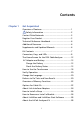
Contents Chapter 1 Get Acquainted Overview of Features ......................................................1 Safety Information ...................................................2 Contact Fluke Networks .................................................5 Register Your Product ....................................................5 Technical Reference Handbook .....................................6 Additional Resources ......................................................
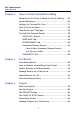
DSX CableAnalyzer Users Manual Chapter 2 How to Certify Twisted Pair Cabling Make Sure Your Tester is Ready to Certify Cabling ..... 29 Set the Reference ........................................................... 30 Settings for Twisted Pair Tests ....................................... 31 How to Do an Autotest .................................................. 36 “Bad Patch Cord” Message ............................................ 38 Twisted Pair Autotest Results .......................................
Contents Copy Project Settings to Other Testers ..........................67 Chapter 5 Maintenance Verify Operation .............................................................70 Clean the Tester ..............................................................70 Traceable Calibration Period ..........................................70 See Information About the Tester .................................70 Update the Software ......................................................
DSX CableAnalyzer Users Manual iv
List of Figures Figure Page 1. Main Tester Connectors, Keys, and LEDs....................... 8 2. Remote Tester Connectors, Keys, and LEDs .................. 10 3. The Home Screen for the DSX CableAnalyzer .............. 12 4. LEDs Show the Remote’s Battery Status........................ 16 5. Connections to See the Status of the Remote’s Battery............................................................. 17 6. How to Zoom the Screen................................................ 19 7.
DSX CableAnalyzer Users Manual 23. How to Connect the Tester to a PC ................................56 24. PROJECT Screen ...............................................................61 25. CABLE ID SETUP Screen (after you enter the first and last IDs) ............................64 26. How to Connect the Tester to a PC ................................72 27. How to Connect Units Together to Update the Software .......................................................74 28.
riešenia na presné meranie Chapter 1: Get Acquainted Overview of Features The Fluke Networks DSX CableAnalyzer™ modules attach to Versiv™ main and remote units to make rugged, hand-held testers that let you certify, troubleshoot, and document twisted pair network cabling. The testers includes these features: DSX-5000 modules certify twisted pair cabling to Class FA limits (1000 MHz) in less than 15 seconds. Gives a PASS or FAIL result based on a test limit that you specify.
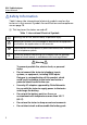
DSX CableAnalyzer Users Manual riešenia na presné meranie Safety Information Table1 shows the international electrical symbols used on the tester or in this manual. Symbols for certifications and compliance are on page 78. : This key turns the tester on and off. Table 1. International Electrical Symbols Warning: Risk of fire, electric shock, or personal injury. Warning or Caution: Risk of damage or destruction to equipment or software. See explanations in the manuals.
riešenia na presné meranie Chapter 1: Get Acquainted Safety Information Do not use the tester if it is damaged. Inspect the tester before use. Do not open the case; no user-serviceable parts are inside. Do not modify the tester. If this equipment is used in a manner not specified by the manufacturer, the protection provided by the equipment can possibly be impaired.
DSX CableAnalyzer Users Manual riešenia na presné meranie Fluke Networks recommends that you save no more than one day of test results on a flash drive. 4 Do not operate portable transmitting devices, such as walkie-talkies and cell phones, during a cable test. Doing so can cause errors in test results. Do not twist, pull on, pinch, crush, or make kinks in the cables on the permanent link adapters. See Figure 9 on page 25. http://www.elso.
riešenia na presné meranie Chapter 1: Get Acquainted Contact Fluke Networks Contact Fluke Networks www.flukenetworks.com support@flukenetworks.
DSX CableAnalyzer Users Manual riešenia na presné meranie Technical Reference Handbook The Versiv Technical Reference Handbook has more information about the tester. The Handbook is on the Versiv Product Manuals CD included with your product, and on the Fluke Networks website. Additional Resources The Fluke Networks Knowledge Base answers common questions about Fluke Networks products and provides articles on cable testing techniques and technology. To access the Knowledge Base, log on to www.
riešenia na presné meranie Chapter 1: Get Acquainted Kit Contents Kit Contents The DSX kit comes with the accessories in the lists below. If something is damaged or missing, contact the place of purchase immediately.
DSX CableAnalyzer Users Manual riešenia na presné meranie Connectors, Keys, and LEDs GPU88.EPS Figure 1. Main Tester Connectors, Keys, and LEDs Connector for a link interface adapter RJ45 jack for communications between the main and remote testers when you do alien crosstalk measurements. See “About the AxTalk Analyzer Kit” on page 28. LCD display with touchscreen 8 http://www.elso.
riešenia na presné meranie Chapter 1: Get Acquainted Connectors, Keys, and LEDs : Starts a test. To start a test, you can also tap TEST on the display. : Power key : Press to go to the home screen. Connector for the AC adapter. The LED is red when the battery charges, and green when the battery is fully charged. The LED is yellow if the battery will not charge. See “Charge the Battery” on page 15. RJ45 connector: For functions available in future software releases.
riešenia na presné meranie DSX CableAnalyzer Users Manual A B C H I D G E F GPU42.EPS Figure 2. Remote Tester Connectors, Keys, and LEDs Connector for a link interface adapter RJ45 jack for communications between the main and remote testers when you do alien crosstalk measurements. See “About the AxTalk Analyzer Kit” on page 28. PASS LED comes on when a test passes. TEST LED comes on during a test. FAIL LED comes on when a test fails. 10 http://www.elso.
riešenia na presné meranie Chapter 1: Get Acquainted Connectors, Keys, and LEDs TALK LED comes on when the talk function is on. LOW BATTERY LED comes on when the battery is low. The LEDs also have these functions: • Battery gauge (see Figure 4 on page 16) • Volume indicator for the TALK function • Progress indicator for software updates : Starts a test. : Power key : Press to use the headset to speak to the person at the other end of the link. Press again to adjust the volume.
riešenia na presné meranie DSX CableAnalyzer Users Manual The Home Screen for the DSX CableAnalyzer The home screen (Figure 3) shows important test settings. Before you do a test, make sure these settings are correct. LM K A B C J D E F G H I GPU110.EPS Figure 3. The Home Screen for the DSX CableAnalyzer PROJECT: The project contains the settings for a job and helps you monitor the status of a job. When you save test results, the tester puts them in the project.
riešenia na presné meranie Chapter 1: Get Acquainted The Home Screen for the DSX CableAnalyzer Shows a summary of the test results in the project: : The number of tests that passed. : The number of tests that failed. : The number of tests with an overall marginal result. The test setup panel shows the settings the tester will use when you tap TEST or press . To change these settings, tap the panel. Note You can set up tests for any module that the tester can use, even when no module is attached.
DSX CableAnalyzer Users Manual riešenia na presné meranie The percentage of the project that is completed. The percentage is the number of IDs used for saved results divided by the total number of used and available IDs in the project. The number of IDs includes IDs for copper and fiber cable. % Tested does not show if your project contains only a Next ID list. See “About Next ID Sets” on page 63 for more information about the Next ID list. The type of module attached to the main Versiv unit.
riešenia na presné meranie Chapter 1: Get Acquainted AC Adapter and Battery AC Adapter and Battery You can use the AC adapter (model VERSIV-ACUN) or the lithium ion battery (model VERSIV-BATTERY) to supply power to the tester. To remove the battery, see “Remove the Battery” on page 75. Charge the Battery Before you use the battery for the first time, charge the battery for about 2 hours with the tester turned off. To charge the battery Connect the AC adapter to the tester. See item in Figure 1.
DSX CableAnalyzer Users Manual riešenia na presné meranie If the AC adapter is not connected, the red bar shows that the battery is very low. Connect the AC adapter to charge the battery and make sure the tester continues to operate. The red bar also shows if the AC adapter is connected, but the battery is not installed. On a remote The LEDs show the battery status at the end of the power-up sequence, as shown in Figure 4. 84 % - 100 % 67 % - 83 % 51 % - 66 % 34 % - 50 % 18 % - 33 % 0 % - 17 % GPU102.
riešenia na presné meranie Chapter 1: Get Acquainted AC Adapter and Battery When the AC adapter is not connected, the screen shows the Time Remaining, which is the approximate battery life at the present rate of use. Permanent link adapter Channel adapter Two channel adapters and a patch cord GPU89.EPS Figure 5. Connections to See the Status of the Remote’s Battery http://www.elso.
DSX CableAnalyzer Users Manual riešenia na presné meranie How to Use the Touchscreen The touchscreen lets you use fingertip gestures to control the tester. You can also operate the touchscreen with a stylus that is made for projected capacitance touchscreens. Caution For correct operation and to prevent damage to the touchscreen: Touch the screen only with your fingers or with a stylus that is made for projected capacitance touchscreens. Do not use too much force.
riešenia na presné meranie Chapter 1: Get Acquainted How to Use the Touchscreen To zoom in, use the reversepinch gesture or the horizontal and vertical zoom controls. To move the image, drag it in any direction. To zoom out, use the pinch gesture or the horizontal and vertical zoom controls. To quickly go back to 1:1 magnification, double-tap the screen. HEJ45.EPS Figure 6. How to Zoom the Screen http://www.elso.
DSX CableAnalyzer Users Manual riešenia na presné meranie Verify Operation The tester does a self test when you turn it on. If the tester shows an error or does not turn on, refer to “If the Tester Does Not Operate as Usual” on page 103. Change the Language On the home screen, tap the TOOLS icon, tap Language, then tap a language.
riešenia na presné meranie Chapter 1: Get Acquainted Buttons to Do Tests and Save Results A B C D E F G GPU40.EPS Figure 7. FIX LATER, TEST AGAIN, and TEST Buttons and the TEST Key SAVE (yellow), TEST (gray): These buttons show if the test passed and Auto Save is off. When you tap SAVE, you can save the results with an ID that you make or select. When you tap TEST, you can select to save the results or do the test again and not save the results.
DSX CableAnalyzer Users Manual riešenia na presné meranie TEST AGAIN: This button shows if the test failed. Tap this button to do the test again for the same ID. If Auto Save is on, the tester saves subsequent results with the same ID. If Auto Save is off, you can save the result if necessary. When you look at a result that failed, tap TEST AGAIN to do the test again for the same ID and with the same test settings as the saved result.
riešenia na presné meranie Chapter 1: Get Acquainted Options for Cable IDs You can use the CABLE ID SETUP screen to make a set of sequential IDs. The tester uses the IDs in sequence as the names for the results you save. When Auto Save is on, the tester automatically saves each result with the next available ID in the set. See Chapter 8. A cable ID set also lets you use IDs again so you can add different results to tests you saved before. You can enter an ID each time you do a test.
DSX CableAnalyzer Users Manual riešenia na presné meranie About Link Interface Adapters Link interface adapters let you connect the DSX CableAnalyzer to different types of twisted pair links. Figure 8 shows how to attach and remove adapters. Caution To prevent damage to the cables on the permanent link adapters and to make sure your test results are as accurate as possible, do not twist, pull on, pinch, crush, or make kinks in the cables. See Figure 9 on page 25. GPU109.EPS Figure 8.
riešenia na presné meranie Chapter 1: Get Acquainted About Link Interface Adapters 5 in (13 cm) minimum GPU108.EPS Figure 9. How to Prevent Damage to the Permanent Link Adapter Cables http://www.elso.
DSX CableAnalyzer Users Manual riešenia na presné meranie How to Install a Strap Two types of straps are available for the tester: a hand strap that helps you hold the tester, and a carrying strap that lets you carry and hang the tester. Figure 10 shows how to install a strap and how to use the hand strap. GPU43.EPS Figure 10. How to Install a Strap and Use the Hand Strap How to Remove or Install a Module Figure 11 shows how to remove and install the module.
riešenia na presné meranie Chapter 1: Get Acquainted How to Remove or Install a Module Removal B A A Installation Caution To prevent damage to the case, push the latches down () before you turn them (). A B C C D D HEJ20.EPS Figure 11. How to Remove and Install a Module http://www.elso.
DSX CableAnalyzer Users Manual riešenia na presné meranie About LinkWare and LinkWare Stats Software The LinkWare Cable Test Management software included with your tester lets you upload test records to a PC, organize and examine test results, print professional-quality test reports, and do software updates and other maintenance procedures on your tester. Updates to LinkWare software are available on the Fluke Networks website.
riešenia na presné meranie Chapter 2: How to Certify Twisted Pair Cabling Warning Before you use the DSX CableAnalyzer, read the safety information that starts on page 2. Make Sure Your Tester is Ready to Certify Cabling To make sure your tester meets its accuracy specifications, follow these guidelines: Keep the tester’s software current. The latest software is available on the Fluke Networks website. See “Update the Software” on page 71.
DSX CableAnalyzer Users Manual riešenia na presné meranie Set the Reference The reference procedure for twisted pair cable sets the baseline for insertion loss, ACR-F, and DC resistance measurements. Set the reference at these times: When you want to use the tester with a different remote. You can set the reference for eight different remotes. When you attach Class F/FA link interface adapters, such as the optional DSX-PLA011 TERA™ adapters. Every 30 days.
riešenia na presné meranie Chapter 2: How to Certify Twisted Pair Cabling Settings for Twisted Pair Tests Permanent link adapter Channel adapter GPU89.EPS Figure 12. Reference Connections for Twisted Pair Cable Settings for Twisted Pair Tests Table 2 gives descriptions of the settings for twisted pair tests. To set up a project, which includes the settings in Table 2, cable IDs, and operator names, see Chapter 4. To set up a twisted pair test 1 On the home screen, tap the test setup panel.
DSX CableAnalyzer Users Manual riešenia na presné meranie Table 2. Settings for Twisted Pair Tests Setting Description Module Select DSX-5000 CableAnalyzer. Cable Type Select a cable type that is correct for the type you will test. To see a different group of cable types, tap MORE, then tap a group. To make a custom cable type, tap Custom in the Cable Groups list. NVP Nominal velocity of propagation. The tester uses the NVP and the propagation delay to calculate the length of the cable.
riešenia na presné meranie Chapter 2: How to Certify Twisted Pair Cabling Settings for Twisted Pair Tests Table 2. Settings for Twisted Pair Tests (continued) Store Plot Data Off : The tester does not save plot data for frequencydomain tests or for the HDTDR/HDTDX analyzers. You can see the plots before you save the test and exit the results screen. The saved results show frequency-domain measurements in a table and do not include the HDTDR/ HDTDX plots.
DSX CableAnalyzer Users Manual riešenia na presné meranie Table 2. Settings for Twisted Pair Tests (continued) AC Wire Map The AC Wire Map test lets you do tests on links connected through midspan PoE (Power over Ethernet) devices. See the Technical Reference Handbook. When the AC Wire Map test is on, this icon shows on the home screen: Note Always turn off the AC wire map test when you will not do tests through a PoE device. The AC wire map test increases the time for an Autotest. 34 http://www.elso.
riešenia na presné meranie Chapter 2: How to Certify Twisted Pair Cabling Settings for Twisted Pair Tests T568A T568B USOC Single-Pair USOC Two-Pair Crossover 1000BASE-T Crossover Rollover 2 x Two-Pair Crossed Ethernet and M12 Two-Pair Ethernet and M12 Two-Pair Crossed Token Ring ATM/TP-PMD Straight ATM/TP-PMD Crossed CSU/DSU GPU85.EPS Figure 13. Outlet Configurations http://www.elso.
DSX CableAnalyzer Users Manual riešenia na presné meranie How to Do an Autotest When you tap TEST on the main tester or press on the main or remote tester, the testers do an Autotest. The Autotest includes all the tests necessary to certify that the cabling meets or exceeds the performance requirements specified in the selected test limit. Figure 14 shows the equipment for Autotests on twisted pair cable. C A D B GPU111.
riešenia na presné meranie Chapter 2: How to Certify Twisted Pair Cabling How to Do an Autotest To do an Autotest on twisted pair cable 1 Attach permanent link or channel adapters to the main and remote testers. 2 Make sure that the home screen shows the correct settings for the job. To make sure that other settings are correct, tap the test setup panel, make sure the correct test is selected on the CHANGE TEST SCREEN, then tap EDIT to see more settings. Table 2 on page 32 describes the settings.
riešenia na presné meranie DSX CableAnalyzer Users Manual Horizontal cabling Optional consolidation point Hub or switch Patch cord from hub or switch Wall outlet Patch panels Patch cord from PC Start channel End channel Tester with channel adapter Remote with channel adapter GPU96.EPS Figure 16. Channel Connections “Bad Patch Cord” Message To comply with standards for tests on channels, the tester removes the effects of the channel adapters and their connections from the test results.
riešenia na presné meranie Chapter 2: How to Certify Twisted Pair Cabling Twisted Pair Autotest Results Twisted Pair Autotest Results The tests listed below apply to twisted pair cabling. Note Some tests are not included in some test limits.
riešenia na presné meranie DSX CableAnalyzer Users Manual PASS*/FAIL* Results A result shows an asterisk when measurements are in the tester’s accuracy uncertainty range (Figure 17) and the asterisk is required by the selected test limit. These results are marginal. A PASS* shows that the cable’s performance is satisfactory. If a cable must get a PASS result to agree with your requirements for quality, identify and correct the problems with the cable and do the Autotest again.
riešenia na presné meranie Chapter 2: How to Certify Twisted Pair Cabling Twisted Pair Autotest Results D E A B C F GPU59.EPS Figure 18. WIRE MAP Tab The name of the outlet configuration used for the test. The outlet configuration is a setting on the TEST SETUP screen. The wire map of the cabling. The main tester is at the left side of the wire map. Tap to see information about wire map faults. If shows, tap it to see a message about the results, such as Bad patch cord at remote.
riešenia na presné meranie DSX CableAnalyzer Users Manual The wire map agrees with the outlet configuration selected for the test. When more than one button shows at the bottom of the screen, the tester highlights one in yellow to recommend which one to tap. See “Buttons to Do Tests and Save Results” on page 20. PERFORMANCE Tab The PERFORMANCE tab (Figure 19) shows the overall result for each test that is required by the selected test limit. C A B D E GPU86.EPS Figure 19.
riešenia na presné meranie Chapter 2: How to Certify Twisted Pair Cabling Twisted Pair Autotest Results The overall result for the Autotest. If the result shows an asterisk, See “PASS*/FAIL* Results” on page 40. The overall result for the test: The results exceed the limit. The results are within the limit. The selected test limit does not have a limit for the test, or a dB rule applies. See the Technical Reference Handbook. The results are within the range of accuracy uncertainty for the tester.
riešenia na presné meranie DSX CableAnalyzer Users Manual A I B H C D E F G GPU104.EPS Figure 20. Tabular Results Screen for a Frequency-Domain Test The location where the tester made the measurements. To switch between results for the main and remote, tap REMOTE or MAIN (). The results are for the wire pair or pairs shown. To see the results for a different pair or pairs, tap a tab on the right side of the screen ().
riešenia na presné meranie Chapter 2: How to Certify Twisted Pair Cabling Twisted Pair Autotest Results The measured value. The limit specified by the selected test limit. MARGIN is the difference between the measured value and the limit. The value is in a red box if the measurement exceeds the limit. To switch between results for the main unit and the remote, tap REMOTE or MAIN. To see the results for a different pair or pairs, tap a tab. The result for the pair.
riešenia na presné meranie DSX CableAnalyzer Users Manual A M B C L D E F K G HI J GPU71.EPS Figure 21. Plot Screen for a Frequency-Domain Test The location of the measurements. To switch between results for the main and remote, tap REMOTE or MAIN (). Measured values for the wire pairs. The limit line (in red) for the measurement. Note If the limit line is black, the tester does not evaluate the measurement at those frequencies because a dB rule applies.
riešenia na presné meranie Chapter 2: How to Certify Twisted Pair Cabling Twisted Pair Autotest Results The vertical scale is the measured value in decibels. The horizontal scale is the frequency range in megahertz. To see help for the screen, tap . To switch between results for the main unit and the remote, tap REMOTE or MAIN. The margin at the cursor’s location. The margin is the difference between the measured value and the limit. The margin is negative if the pair failed.
DSX CableAnalyzer Users Manual riešenia na presné meranie DIAGNOSTIC Tab If the Autotest failed or had a marginal result, or if you selected All Autotests for the HDTDR/HDTDX setting on the TEST SETUP screen, the DIAGNOSTIC tab gives you access to the HDTDR and HDTDX analyzer plots. The plots help you locate the causes of NEXT and return loss failures. See the Technical Reference Handbook. 48 http://www.elso.
riešenia na presné meranie Chapter 3: Test Results View Saved Results On the home screen, tap the RESULTS icon. The RESULTS screen shows the results in the active project. See Figure 22. To organize results and make reports you can give to customers, use LinkWare software. http://www.elso.
riešenia na presné meranie DSX CableAnalyzer Users Manual A J B C D I E F G H HEJ24.EPS Figure 22. RESULTS Screen The name of the active project. : The number of results that passed. This includes individual results for each ID and tests that have an result. : The number of results that failed. This includes individual results for each ID. : The number of results that have measurements within the range of accuracy uncertainty for the tester. See “PASS*/FAIL* Results” on page 40.
riešenia na presné meranie Chapter 3: Test Results View Saved Results Note These numbers show the total number of results that passed and failed in the IDs saved. So, the numbers can be more than the number of IDs saved. The cable IDs that have FAIL results and must be tested again. Because some IDs can have one or more tests that failed, the number at the top of this screen () can be more than the number of retests needed.
DSX CableAnalyzer Users Manual riešenia na presné meranie How to Replace a Saved Result that Failed To use the same test settings that were used for the saved result 1 On the home screen, tap the RESULTS icon. 2 On the RESULTS screen, tap a result that failed. 3 Tap TEST AGAIN. 4 When the test is completed, and if Auto Save is on, the tester asks you if you want to overwrite the results. Tap Yes.
riešenia na presné meranie Chapter 3: Test Results Delete, Rename, and Move Results To delete results 1 On the MANAGE RESULTS screen, select the results you want to delete. To select all the tests that failed or all the tests that passed, tap Select All Retests or Select All Passes. 2 Tap DELETE, then tap DELETE in the confirmation dialog. To rename results 1 On the MANAGE RESULTS screen, select one result to rename. 2 Tap RENAME. 3 Enter a new name, then tap DONE.
DSX CableAnalyzer Users Manual riešenia na presné meranie Manage Results on a Flash Drive You can export or import results to or from a flash drive, and delete results on the flash drive. Caution Do not remove the USB flash drive while the LED on the drive flashes. Doing so can corrupt the data on the drive. You can lose a USB flash drive, cause damage to it, or accidentally erase the contents of the drive.
riešenia na presné meranie Chapter 3: Test Results Upload Results to a PC Note Cable IDs are case-sensitive. For example, the tester saves result with the names “A0” and “a0” in two different records. If you select the active project, the EXPORT RESULTS screen shows the percentage of tests completed for the project and the percentage of results already exported to a flash drive.
DSX CableAnalyzer Users Manual riešenia na presné meranie Type A USB port Micro-AB USB port GPU46.EPS Figure 23. How to Connect the Tester to a PC 56 http://www.elso.
riešenia na presné meranie Chapter 3: Test Results View the Memory Status View the Memory Status To see the memory status On the home screen, tap the TOOLS icon, then tap Memory Status. The MEMORY STATUS screen shows these values: The percentage of memory available The number of test records that are saved The number of .
DSX CableAnalyzer Users Manual 58 riešenia na presné meranie http://www.elso.
riešenia na presné meranie Chapter 4: Projects Why Use Projects? Projects help you monitor the status of a job and make sure that your work agrees with the requirements of the job. You can use a project to do these tasks: Specify the tests that are necessary for a job. Specify settings for tests. Specify an operator for the job. Make sets of sequential IDs to use as names for test results. Automatically save test results with IDs from a set.
DSX CableAnalyzer Users Manual riešenia na presné meranie Set Up a Project Refer to the PROJECT screen in Figure 24 on page 61. 1 On the home screen, tap the PROJECT panel, tap CHANGE PROJECT, then tap NEW PROJECT. 2 On the NEW PROJECT screen, enter a name for the project, then tap DONE. 3 On the PROJECT screen, tap the Operator panel to enter an operator name for the project. 4 On the PROJECT screen, tap the NEW TEST button to enter the tests and test settings necessary for the project.
riešenia na presné meranie Chapter 4: Projects The PROJECT Screen A B C D E J F J G H I GPU08.EPS Figure 24. PROJECT Screen The name of the project. See also item . Operator: The name of the person who will do the tests for the project. The date range for the results in the project. Results: A summary of the test results in the project: : The number of tests that failed. : The number of tests that passed.
DSX CableAnalyzer Users Manual riešenia na presné meranie Test Setup: The tests that are available in the project. To add a test to the project, tap NEW TEST. Cable ID Sets: The sets of IDs the tester can use for the names of test results. Each ID set is for either copper or fiber cable. To add a set of IDs to the project, tap NEW ID SET. See Figure 25. To use a different project, tap CHANGE PROJECT, then tap a project. To make a new project, tap CHANGE PROJECT, then tap NEW PROJECT.
riešenia na presné meranie Chapter 4: Projects The CABLE ID SETUP Screen The CABLE ID SETUP Screen To see the CABLE ID SETUP screen, tap the PROJECT panel on the home screen, then tap NEW ID SET on the PROJECT screen. See Figure 25 on page 64. Each project can have up to 5000 IDs. If an ID set does not have a Last ID, the tester counts the set as one ID. An ID can have a maximum of 60 characters. Symbols, such as the asterisk, and accented characters do not increment.
riešenia na presné meranie DSX CableAnalyzer Users Manual example, if you have one Next ID set and one set with 10 IDs, and you save 10 results with next IDs, the % Tested shows 50% (10 saved results divided by 20 IDs). A B C D E F HEJ09.EPS Figure 25. CABLE ID SETUP Screen (after you enter the first and last IDs) 64 http://www.elso.
riešenia na presné meranie Chapter 4: Projects About Next ID Sets First ID and Last ID: The first and last IDs in a set of sequential IDs. If you do not enter a Last ID when you make an ID set, the tester will increment the First ID to make subsequent IDs. Note The tester does not increment symbols or accented characters. When you use an ID set that does not have a Last ID, the set under IDs Untested on the CHANGE ID screen shows only the next ID. Total IDs: The number of IDs in the set.
DSX CableAnalyzer Users Manual riešenia na presné meranie Manage Projects on a Flash Drive You can export or import projects to or from a flash drive, and delete projects on the flash drive. The project data includes all project settings and test results. Caution Do not remove the USB flash drive while the LED on the drive flashes. Doing so can corrupt the data on the drive. You can lose a USB flash drive, cause damage to it, or accidentally erase the contents of the drive.
riešenia na presné meranie Chapter 4: Projects Copy Project Settings to Other Testers Copy Project Settings to Other Testers To copy the settings in a project to other Versiv units, use the Read Project Setups and Write Project Setups utilities in LinkWare software. You can use LinkWare to read project settings from a tester or from a project you exported to a flash drive. http://www.elso.
DSX CableAnalyzer Users Manual 68 riešenia na presné meranie http://www.elso.
riešenia na presné meranie Chapter 5: Maintenance Warning To prevent possible fire, electric shock, personal injury, or damage to the tester: Do not open the case. You cannot repair or replace parts in the case. Use only replacement parts that are approved by Fluke Networks. If you replace parts that are not specified as replacement parts, the warranty will not apply to the product and you can make the product dangerous to use. Use only service centers that are approved by Fluke Networks.
DSX CableAnalyzer Users Manual riešenia na presné meranie Verify Operation The tester does a self test when you turn it on. If the tester shows an error or does not turn on, refer to “If the Tester Does Not Operate as Usual” on page 76. Clean the Tester To clean the touchscreen, turn off the tester, then use a soft, lintfree cloth that is moist with water or water and a mild detergent. To clean the case, use a soft cloth that is moist with water or water and a mild detergent.
riešenia na presné meranie Chapter 5: Maintenance Update the Software To see information about a remote tester Use DSX CableAnalyzer modules and adapters to connect the main and remote testers together (see Figure 5 on page 17), then tap REMOTE on the Version Information screen. Update the Software New software gives you access to new features and the latest test limits and cable types. Software updates are available on the Fluke Networks website.
DSX CableAnalyzer Users Manual riešenia na presné meranie 4 On the LinkWare menu, select Utilities > DSX CableAnalyzer > Software Update, find and select the update file, then click Open. LinkWare saves the update file on the tester, then the tester installs the file. 5 The tester reboots when the update is completed.
riešenia na presné meranie Chapter 5: Maintenance Update the Software To use an updated main unit to update a remote or another main unit 1 Turn on both testers and connect the AC adapters to both testers. 2 Use the USB cable provided to connect the updated main unit to the remote or to another main. See Figure 27. 3 Follow the instructions shown on the display of the updated main unit.
DSX CableAnalyzer Users Manual riešenia na presné meranie AC adapter AC adapter Updated main unit Type A USB port Remote Micro-AB USB port AC adapter AC adapter Updated main unit Main unit Type A USB port Micro-AB USB port GPU116.EPS Figure 27. How to Connect Units Together to Update the Software 74 http://www.elso.
riešenia na presné meranie Chapter 5: Maintenance Extend the Life of the Battery Extend the Life of the Battery Do not frequently let the battery discharge completely. Do not keep the battery at temperatures below -20 oC (-4 oF) or above +50 oC (+122 oF) for periods longer than one week. Before you put a battery into storage, charge it to approximately 50 % of full charge.
DSX CableAnalyzer Users Manual riešenia na presné meranie B C A OFF Model VERSIV-BATTERY GPU21.EPS Figure 28. How to Remove the Battery Calibration To make sure that the modules operate within the published specifications for accuracy, have them calibrated at a Fluke Networks authorized service center every 12 months. To get information on factory calibration, contact an authorized Fluke Networks Service Center.
riešenia na presné meranie Chapter 5: Maintenance Options and Accessories You can also use LinkWare software to upload the system log from the tester. This file contains information that can possibly help Fluke Networks find a solution to an unusual problem. To see the serial numbers of the main and remote units and modules if the tester is not operating correctly, remove the module and look at the stickers under and on the module. Table 3.
DSX CableAnalyzer Users Manual riešenia na presné meranie Certifications and Compliance Conformite Europeene. Conforms to the requirements of the European Union and the European Free Trade Association (EFTA). Listed by the Canadian Standards Association. Conforms to relevant Australian standards. Conforms to relevant Russian standards.
riešenia na presné meranie Index Symbols channel connections, 38 cleaning case, 70 touchscreen, 70 connectors on the testers, 8 contact Fluke Networks, 5 customer support, 5 * in results, 40 % Tested, 14 –A– ac adapter, 15 AC wire map, 34 accessories ordering, 77 standard, 7 alien crosstalk, 28 asterisk in results, 40 auto save description, 23 how to turn on, 23 Autotest asterisk in results, 40 do an Autotest, 36 results, 39 settings, 31 AxTalk, 28 –D– diagnostic tab, 48 display cleaning, 70 how to use
DSX CableAnalyzer Users Manual riešenia na presné meranie import, 65 make an ID set, 63 maximum number of IDs, 63 next ID, 63, 65 options, 22 –K– Knowledge Base, 6 –L– language, 20 link interface adapters, 24 LinkWare and LinkWare Stats, 28 –M– maintenance, 69 memory capacity, 22 flash drive projects, 66 results, 54 status, 22, 57 upload results to a PC, 55 module connectors, 8 install or remove, 26 twisted pair settings, 32 –N– next ID about next ID sets, 63 on home screen, 13 NVP, 32 –O– operator,
riešenia na presné meranie Index version, 70 storage, 75 store plot data, 33 system log, 77 –T– talk, 14 test again, 22 test limit, 32 test setup add to a project, 62 copy, 62 delete, 62 touchscreen cleaning, 18 how to use, 18 twisted pair See also Autotest reference, 30 results, 39 settings, 31 test, 37 –V– version information, 70 –W– warnings, 69 wire map AC wire map setting, 34 results, 41 http://www.elso.
DSX CableAnalyzer Users Manual 82 riešenia na presné meranie http://www.elso.