2 TM MicroScanner Cable Verifier Getting Started Guide PN 2739668 (English) January 2007 ©2007 Fluke Corporation. All rights reserved. Printed in China. All product names are trademarks of their respective companies.
LIMITED WARRANTY AND LIMITATION OF LIABILITY Fluke Networks guarantees this product to be free from defects in material and workmanship for one year from the date of purchase. Parts, accessories, product repairs and services are warranted for 90 days, unless otherwise stated. Ni-Cad, Ni-MH and Li-Ion batteries, cables or other peripherals are all considered parts or accessories.
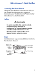
MicroScanner2 Cable Verifier Accessing the Users Manual This guide provides basic information to help you get started using the tester. For additional information, see the MicroScanner2 Cable Verifier Users Manual on the Product CD. Safety WWarningX To avoid possible fire, electric shock, personal injury, damage to equipment, or inaccurate test results, read the safety information in the MicroScanner2 Cable Verifier Users Manual before using the tester.
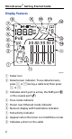
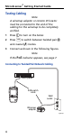
MicroScanner2 Getting Started Guide Display Features O P egs02.eps A Tester icon B Detail screen indicator. To see detail screens, press E or Dduring a cable test; then press E or D.
Changing the Length Units J Telephone voltage indicator. P and N appear in the wiremap diagram over the positive (tip) and negative (ring) wires. K Indicates a wiremap adapter is connected to the far end of the cable L Low battery indicator M Indicates an ID locator is connected to the far end of the cable and shows the locator’s number N Ethernet port indicator O Wiremap diagram. The rightmost segments indicate the shield. P The Windicates a fault or high voltage on the cable.
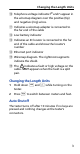
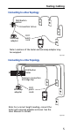
MicroScanner2 Getting Started Guide Testing Cabling Note A wiremap adapter or remote ID locator must be connected to the end of the cabling for the wiremap to be completely verified. 1 Press X to turn on the tester. 2 Press Y to switch between twisted pair (U) and coaxial (T) modes. 3 Connect as shown in the following figures. Note If the PoE indicator appears, see page 7. Connecting to Twisted Pair Network Cabling Patch panel RJ45 patch cords Wall outlet Wiremap adapter egs03.
Testing Cabling Connecting to a Bus Topology Distribution center Connection to bus RJ11 patch cord Wiremap adapter Note: Locations of the tester and wiremap adapter may be swapped. egs17.eps Connecting to a Star Topology Distribution center Common connection to bridge tap Wiremap adapter RJ11 patch cords Note: For a correct length reading, connect the tester and wiremap adapter as shown. See the Users Manual for details. egs16.
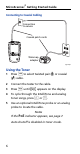
MicroScanner2 Getting Started Guide Connecting to Coaxial Cabling Connection to service Coaxial patch cords Wiremap adapter egs19.eps Using the Toner 1 Press Y to select twisted pair (U) or coaxial (T) cable. 2 Connect the tester to the cable. 3 Press M until L appears on the display. 4 To cycle through the IntelliTone and analog toner songs, press E or D. 5 Use an optional IntelliTone probe or an analog probe to locate the cable. Notes If the PoE indicator appears, see page 7.
Detecting Power Over Ethernet Detecting Power Over Ethernet The tester can detect PoE voltages from active 802.3af sources. To select PoE mode, press Muntil PoE appears on the display. In PoE mode, the tester solicits PoE power on pairs 1,2-3,6 and 4,5-7,8. The tester may activate a PoE source and will not be damaged by PoE power. If PoE power is detected, Poeappears above the powered pairs. The Poemay blink as the PoE source turns the power on and off.
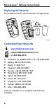
MicroScanner2 Getting Started Guide Replacing the Batteries The batteries last for about 20 hours of typical use. egs28.eps Contacting Fluke Networks www.flukenetworks.com support@flukenetworks.