® 114, 115, 116, and 117 Digital Multimeters Calibration Information Introduction XWWarning To avoid electric shock or injury, do not perform the performance tests or calibration adjustment procedures unless qualified to do so. The information provided in this document is for the use of qualified personnel only.
114, 115, 116, and 117 Calibration Information Safety Information "Warning" and "Caution" Statements A “XW Warning" identifies hazardous conditions and actions that could cause bodily harm or death. A "W Caution" identifies conditions and actions that could damage the Meter, the equipment under test, or cause permanent loss of data.
Digital Multimeters International Electrical Symbols International Electrical Symbols Table 1 lists the international symbols that appear in this document and on the Meter. Table 1. Electrical Symbols Symbol Description Symbol I Description B AC (Alternating Current) F DC (Direct Current) T Double Insulated X Hazardous voltage W Important Information; Refer to manual N Battery (Low battery when shown on the display.
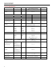
114, 115, 116, and 117 Calibration Information Accuracy Specifications Function Range DC millivolts DC Volts [2] Auto-V LoZ True-rms [2] AC millivolts True-rms Resolution 600.0 mV 0.1 mV 6.000 V 0.001 V 60.00 V 600.0 V 0.01 V 0.1 V 600.0 V 0.1 V 600.0 mV 0.1 mV Accuracy ± ([% of Reading] + [Counts]) Model [1] 0.5 % + 2 114, 115, 116, 117 0.5 % + 2 114, 115, 116, 117 DC, 45 to 500 Hz 500 Hz to 1 kHz 2.0 % + 3 4.0 % + 3 45 to 500 Hz 500 Hz to 1 kHz 1.0 % + 3 2.
Digital Multimeters Basic Maintenance Accuracy Specifications (cont) Function Hz (V or A input) [3] Range Resolution 99.99 Hz 0.01 Hz 999.9 Hz 0.1 Hz 9.999 kHz 50.00 kHz 0.001 kHz 0.01 kHz Accuracy ± ([% of Reading] + [Counts]) Model 0.1 % + 2 [1] 115, 116, 117 Notes: [1] Models listed in this column also refer to the “C” version of the model. For example, those rows containing model 115 are applicable to the 115C as well.
114, 115, 116, and 117 Calibration Information VoltAle rt LTIMETER 117 TRUE RMS MU <.5 AUTO-V LoZ MIN MAX OFF OK OK Lo / H HOLD RANGE Hz V V mV V olt Alert A A A Hz V COM 10 A FUSED erc010f.emf Figure 1. Fuse Testing Replacing the Battery and Fuse XWWarning To avoid shock, injury, or damage to the Meter: • Remove test leads from the Meter before opening the case or battery door. • Use ONLY a fuse with the amperage, interrupt voltage, and speed ratings specified.
Digital Multimeters Performance Tests 2. Remove the Meter from its holster. 3. Remove two screws from the case bottom. 4. Separate the case bottom from the case top. 5. Remove the fuse from its holder and replace with an 11 A, 1000 V, FAST fuse having a minimum interrupt rating of 17,000 A. Use only Fluke PN 803293. 6. To re-assemble the Meter, attach the case bottom to the case top and secure with the two screws. Insert the Meter into its holster.
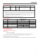
114, 115, 116, and 117 Calibration Information Table 2. Required Equipment (cont) Recommended Equipment Measurement Function 5500A Multi-product Calibrator (or equivalent) Frequency (115, 116, and 117) Fluke 80 AK K-type Thermocouple Adapter Accessory Temperature (116) K-type Thermocouple, mini-plug on both ends Temperature (116) Double Banana plug VoltAlert (117) Accuracy 2 V, 50 kHz ±0.025 % Testing the Display Push K and turn the rotary switch to the e position.
Digital Multimeters Performance Tests 2. Warm up the calibrator as required by its specifications. 3. Allow the temperature of the UUT to stabilize at room temperature (23 °C ± 5 °C [73 °F ± 9 °F] ). 4. Check the fuses and Battery, and replace them if necessary. Refer to “Testing the Fuses”, and “Replacing the Battery and Fuse”. To verify the accuracy of the DMM functions, do the following: 1. Connect the Calibrator to the VΩ and COM input terminals on the Meter. 2.
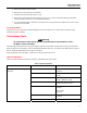
114, 115, 116, and 117 Calibration Information Table 3. DMM Performance Tests (cont) Display Reading Step Function Range Applied [1] 114 18 L 115[1] 116[1] 6.000V 0V -0.002 to 0.002 6.000V 5V 4.973 to 5.027 20 60.00V 50V 49.73 to 50.27 21 600.0V 600V 596.8 to 603.2 22 600.0V -600V -596.8 to -603.2 600.0 mV 6 mV, 45 Hz 600.0 mV 600mV, 1 kHz 600.0 mV 10 mV 9.7 to 10.3 600.0 mV 600mV 596.8 to 603.2 19 23 24 25 26 DC Volts m AC Millivolts • DC Millivolts 117[1] 5.
Digital Multimeters Performance Tests Table 3. DMM Performance Tests (cont) Display Reading Step Function Range Applied [1] 114 41 VoltAlert VoltAlert 116[1] 117[1] N/A Refer to steps 1 – 5 in the procedure below N/A Refer to steps 6 – 9 in the procedure below Hi N/A 42 115[1] N/A Lo N/A N/A [1] If using a Fluke 9100 calibrator, the Calibrator Frequency mode must be used to obtain accurate frequency.
114, 115, 116, and 117 Calibration Information NORMAL AUX V RTD A SENS E A UX V SCOPE OUT 7 TRIG 8 4 5 VoltAlert 117 TRUE RMS MULTIMETER S TB Y . 2 +/0 . Insert Double Banana Center Meter top on Hi terminal. Note that LED is RED erc013f.emf Figure 4. VoltAlert Testing 8. Hold the Meter so that the top is vertically and horizontal centered to the banana plug’s Hi terminal. Verify that the Meter’s beeper is sounding continuously and the red LED at the top of the display lights. 9.
Digital Multimeters Calibration Adjustment 2. Press g once to see the calibration counter. 3. Press g again to start the password entry. The Meter displays “?>>>” 4. The Meter buttons indicated below represent the numbers 1 through 5 when entering or changing the password: K=1 M=2 q=3 g=4 Q=5 5. Press 4 buttons to enter the current password. If changing the password for the first time, enter K (1), M (2), q (3), and g (4). 6. Press qto change the password.
114, 115, 116, and 117 Calibration Information Meter Buttons Used in the Calibration Steps When performing the Calibration Adjustment Procedure, the Meter buttons behave as follows. This may be of help determining why a calibration step is not accepted and for determining the input value without referring to Table 4. Press and hold K to show the measured value. The measured value is not calibrated so it may not match the input value. This is normal. Press and hold M to display the required input value.
Digital Multimeters Calibration Adjustment Notes Set the calibrator to Standby prior to changing the function switch position and after completing adjustment of each function. If the calibration adjustment procedure is not properly completed, the Meter will not operate correctly. Table 4.
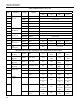
114, 115, 116, and 117 Calibration Information Table 4. Calibration Adjustment Steps (cont) Rotary Switch Position $ Calibration Steps 114 N/A [1] 115 N/A [1] 116 C/23 [1,2] 117 N/A Input Terminals + and COM Calibrator Source Value 600 μA, 0 Hz DC μamps 16 [1] Models listed in this column also refer to the “C” version of the model. For example, model 115 steps are valid for the 115C. [2] Do not calibrate the 117 or 117C with a line-frequency power source nearby (e.g.
Digital Multimeters Replacement Parts Replacement Parts Table 5 lists the Meter’s replacable parts identified in Figure 6. 6 5 8 12 3 9 1 10 4 2 7 11 15 4 PL 23 13 16 17 2 PL 19 20 14 18 21 22 erc14.emf Figure 6.
114, 115, 116, and 117 Calibration Information Table 5. Replacable Parts List Item Description Part Number Qty. 1 LCD,FLUKE-11X,3.2V,TN,4-DIGIT,1/4-DUTY,1/3-BIAS,LEPTON 2509955 2 CONNECTOR,ELASTOMERIC,.010 IN CTR,.218 IN HIGH,.090 IN THK,2.
Digital Multimeters Warranty Table 5. Replaceable Parts List Item Part Number Description Qty. BATTERY,PRIMARY,MNO2ZN,9V,505MAH,6LR61,ALKALINE, 17X26X48MM,BULK 614487 20 FLUKE 12-8004,SHOCK ABSORBER 878983 1 21 FLUKE-117-2005,TILT STAND 2525594 1 FLUKE-117-2005,TILT STAND, 11X China 2631071 1 FLUKE-117-2010,HOLSTER 2525649 1 FLUKE-117-2010,HOLSTER, 11X China 2631080 1 23 FUSE,11A,1000V,FAST.406INX1.
114, 115, 116, and 117 Calibration Information 20