
Application Note

2 Fluke Corporation Fluke ScopeMeter
®
125 helps solve a Modbus RS-485 timing problem
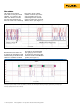
Next Roach set the Fluke 125
to capture the waveform at 500
microseconds per division. This
allowed a resolution at which
he could see each individual
byte going by and was able
to capture the three bytes that
were the header of the Modbus
packet. (See Figure 2.)
The solution
“My usual serial analysis
tools didn’t do the job,” Roach
explains, “so I turned to the
Fluke 125. What it revealed
that the serial analyzer had
failed to reveal was a relatively
long pause—about 7 milli-
seconds—between byte three
and everything else. It was
something that the customer
pointed to right away and said,
‘What’s that?’” (See Figure 1.)
Figure 1. This data capture at 5 ms/div reveals both the poll and the response. Notice the delay of approximately 7 ms in the response.
Figure 2. The data capture of the first three bytes of the Modbus RTU response at 500 µs/div. This representation includes a decoding of
the response signal to clarify the slave node address, the function code and response data length in bytes (represented by the binary logic
manually superimposed above the waveform).
500ms/Div
500 µs/div
-1.00 ms
Input A