
Application Note

Fluke. Keeping your world
up and running.
®
Fluke Corporation
PO Box 9090, Everett, WA 98206 U.S.A.
Fluke Europe B.V.
PO Box 1186, 5602 BD
Eindhoven, The Netherlands
For more information call:
In the U.S.A. (800) 443-5853 or
Fax (425) 446-5116
In Europe/M-East/Africa +31 (0) 40 2675
200 or
Fax +31 (0) 40 2675 222
In Canada (800)-36-FLUKE or
Fax (905) 890-6866
From other countries +1 (425) 446-5500 or
Fax +1 (425) 446-5116
Web access: http://www.fluke.com
©2008 Fluke Corporation.
Specifications subject to change without notice.
Printed in U.S.A. 3/2008 3306965 A-EN-N Rev A
Roach further explains that
the MicroLogix serial port in
Modbus RTU master mode has
a settable inter-character time
value. The default value of
zero applies the Modbus RTU
3.5 byte time to the port. “We
adjusted this value,” he reveals,
“and found that a value of 10
milliseconds made communica-
tions between the MicroLogix
1100 and the analog block
device work perfectly.”
In summary, Roach says, “I
was pretty sure I could solve
almost any Modbus RTU or DF1*
issue with my serial analyz-
ers, but their timestamps aren’t
accurate enough to find this
kind of delay inside a serial
data string. The Fluke 125,
which did a good job showing
the serial rate as well as the
max-min waveform values, was
an excellent tool for trouble-
shooting this situation.”
* DF1 is a Serial Communications Protocol
used by most of Rockwell Automation’s
(Allen-Bradley) programmable controllers.
3 Fluke Corporation Fluke ScopeMeter
®
125 helps solve a Modbus RS-485 timing problem
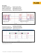
Bytes, bits and waveforms
In Figure 2, the waveform at
500 microseconds per division,
the oscilloscope displayed left-
to-right the sequence in which
these bytes were coming down
the wire. What an analyst must
remember, especially an analyst
who is not completely conver-
sant in how bytes and bits tie
to waveforms, is that the usual
way of decoding these things
on paper is to write “the least
significant bit” on the right of
the page. However, when look-
ing at a byte on the oscilloscope,
remember that it’s the other way
around—left to right.
In addition, one must under-
stand also “serial framing.” Even
though a byte that comes across
a serial line has only eight bits
of data, there are actually ten
bits on the line because there’s
a stop bit and a start bit. That’s
easy to forget, because there is
no space or time between the
stop and start bits.
Conclusion
A Modbus RTU poll response
begins with the slave node
address, the function code,
and the response data length
in bytes. Typically, these data
are followed by the response
data and the CRC checksum.
A close look at the data packet
in Figure 2 allows one to see
that this first short data packet
consisted of the values 1, 3,
and 64. That is the correct
response before the actual
data values for the polling of
Modbus Node 1 with function
code 3 for 32 words (64 bytes).
Roach conjectures that the
thermistor monitoring block
lacked sufficient CPU power to
make a complete response that
included response data and
the CRC checksum, without
pausing to “catch its breath.”
If that is the case, the little
device might respond to the
Modbus RTU poll with the first
three bytes, then pause seven
milliseconds before it sends the
data itself.
Roach notes that the Modbus
RTU specification says that
any idle space of more than
3.5 byte widths is considered
the end of the frame and the
beginning of another. Clearly,
the response was timing out.