® Fluke 125 Industrial ScopeMeter Getting Started GB Dec 2006, Rev. 1, 09/2009 © 2006, 2009 Fluke Corporation, All rights reserved. Printed in The Netherlands All product names are trademarks of their respective companies.
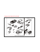
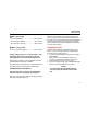
Contents of the Fluke 125 Test Tool Kit S-Version (2x) (3x) Figure 1.
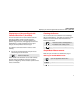
Getting Started Introduction Safety Information: Read First This Getting Started Manual provides basic information on the Fluke 125 ScopeMeter Test Tool. For complete operating instructions, refer to the Users Manual on the accompanying CD-ROM The Fluke 125 ScopeMeter Test Tool (hereafter referred to as “Test Tool”) complies with: Contacting a Service Center To locate a Fluke authorized service center, visit us on the World Wide Web at: www.fluke.
Fluke 125 Getting Started Warning To avoid electrical shock or fire: • Use only the power supply, Model PM8907 (Battery Charger / Power Adapter). • Before use check that the selected/indicated voltage range on the PM8907 matches the local line power voltage and frequency. • For the PM8907/808 universal Battery Charger/Power Adapter use only line cords that comply with the local safety regulations.
Getting Started Preparing for Use Max. Input Voltages Input A and B directly ............................... 600 V CAT III Input A and B via BB120 .......................... 300 V CAT III Input A and B via STL120......................... 600 V CAT III Max. Floating Voltage From any terminal to ground .................... 600 V CAT III Voltage ratings are given as “working voltage”. They should be read as Vac-rms (50-60 Hz) for AC sine wave applications and as Vdc for DC applications.
Fluke 125 Getting Started Powering/Resetting the Test Tool Turning power on/off: Press CONTRAST. The Test Tool powers up in its last setup configuration. Resetting the Test Tool to the factory (default) settings: + Turn power off, then press and hold the Backlight key and turn on again. You should hear a double beep. Changing Backlight and Contrast To save battery power, the screen can be set to an economic brightness display when operated on the battery pack (with no power adapter connected).
Getting Started Making Menu Selections Menu area (C): Displays the menu that provides choices available through the blue arrow keys and the ENTER key: Making Menu Selections Selection of a function in the menu is done as follows: + A menu pops up after operation of, for instance, the MENU key. Use the arrow keys to highlight for example the SCOPE/METER mode. Press ENTER to confirm the selection. The input A measurements menu pops up. Use the arrow keys to highlight the desired measurement function.
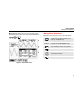
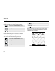
Fluke 125 Getting Started Input Connections and Grounding For Voltage measurements use the Shielded Test Leads on Input A (red) and/or Input B (grey). For Current measurements use a current probe on Input A and/or Input B. For Power measurements use a voltage probe on Input A and a current probe on Input B. Figure 3. Grounding with Unshielded Ground Lead. For Temperature measurements use a 1 mV/°C or 1 mV/°F temperature probe (optional) on Input A and/or Input B.
Getting Started Displaying an Unknown Signal with Connect-and-View™ (Auto Set) Displaying an Unknown Signal with Connect-and-View™ (Auto Set) The Connect-and-View™ function enables hands-off operation to display complex unknown signals in SCOPE/METER mode. This function optimizes the position, range, time base, and triggering and assures a stable display on nearly all waveforms. If the signal changes, the setup will track these changes.
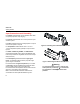
Fluke 125 Getting Started Scope Measurements on Input A and B Choose ac voltage (Vac) measurement for Input A: Open the PEAK Submenu. Highlight PEAK-PEAK. Open the A MEASUREMENTS menu. Press ENTER to confirm the selection. Highlight Vac. Press ENTER to confirm the selection. Now you will see a screen like in Figure 5. The A and B traces give a graphical representation of the waveforms applied to Input A and Input B. Observe that Vac (rms V∼) is now the Main Reading.
Getting Started Scope/Meter Measurements Changing the Waveform Representation Changing the amplitude: Enlarge or reduce the waveform amplitude; there are separate keys for Input A and Input B. Enables the arrow keys for Trigger Level and Slope. Adjust the Trigger Level. Select Negative / Positive Slope. Changing the Time Base: Making Cursor Measurements Increase or decrease the number of periods.
Fluke 125 Getting Started Select the cursor to be moved. Use the blue arrow keys to move the cursors Depending on cursor measurement type: Cursor measurements on trace A or B. Automatic or manual risetime measurement on a single channel. Switch cursor measurements off. Input A and Input B Measurement Menu • In the Input A and input B measurement menu you can choose from many measurement functions. Selection is done with the arrow keys and activated with F4.
Getting Started Scope/Meter Measurements Trigger Options Waveform/Reading Smooth Options Open the application mode menu. Open the application mode menu. Open the TRIGGER menu: Open the SMOOTH menu: INPUT: WAVEFORM: • A, B: Triggering on the input A or input B waveform. • EXT: external triggering via an optically isolated trigger probe. • VIDEO on A…: triggering on video signals via input A. • ENVELOPE: envelope records all values of live waveforms.
Fluke 125 Getting Started Harmonics Measurements Use a voltage probe on Input A and a current probe on Input B. Selecting the Harmonics mode Open the application mode menu. Highlight HARMONICS Enter the harmonics mode. If the Input A probe setting is not V (voltage), or the input B probe setting is not (m)V/A (current), a probe menu pops up to enable you to select the required probe. Selecting the Probe Type Open the PROBE on A or the PROBE on B menu, then select the probe type.
Getting Started Fieldbus Measurements Fieldbus Measurements Bus Health Screen Connect the bus to Input A, and depending on the bus type also to input B. The following icons are used to indicate the bus measurement status: Selecting the Fieldbus Mode and Bus Type bus activity indicators. Choose for example the Modbus, subtype IEA-232/ RS-232: Bus activity indicator 1: : voltage measured { (open) : no voltage measured Open the application mode menu. Highlight BUSHEALTH Enter the BUSHEALTH mode.
Fluke 125 Getting Started Bus Health Screen Softkey Functions Setting up the Limits The bus health screen shows a softkey button bar like the one shown below: To set up the test limits of the current bus type, do the following: Select the SETUP LIMITS… menu from the bus health screen. Select the signal property. Select the Limit Setup function, see below. Select the LOW, HIGH, or WARNING level. Select the voltage level reading. Change the limit. Continue with other limits.
Getting Started Plotting Measurements over Time (TrendplotTM) Plotting Measurements over Time (TrendplotTM) Trendplot Screen Softkey Functions Stop the Trendplot. The TrendPlot™ function plots a graph derived from the MAIN (large) readings in the SCOPE/METER mode or in the HARMONICS mode as a function of time. TREND RESTART: Start a new Trendplot. Turning the Trendplot Mode On/Off MIN MAX AVERAGE: Secondary (small) reading is the minimum, maximum, or average value since the Trendplot start.
Fluke 125 Getting Started User Options Menu • USER OPTIONS gives submenus to configure the Test Tool to your personal taste. • The function keys F1, F2, and F3 give access to submenus: BATTERY REFRESH.. : should be done about four times a year to keep the batteries in optimal condition. LANGUAGE: the language of messages can be selected in this submenu. VERSION & CAL ... shows version and calibration information. 16 SAVE / PRINT Functions Show the PRINT SCREEN, RECALL DELETE… and SAVE… key labels.