
User's Manual

Fluke 125
Getting Started
6
Input Connections and Grounding
For Voltage measurements use the Shielded Test Leads
on Input A (red) and/or Input B (grey).
For Current measurements use a current probe on Input
A and/or Input B.
For Power measurements use a voltage probe on Input A
and a current probe on Input B.
For Temperature measurements use a 1 mV/°C or
1 mV/°F temperature probe (optional) on Input A and/or
Input B.
For OHMΩ, CONTinuity, DIODE, and CAPacitance
measurements (Meter mode) use the Red Shielded Test
Lead at Input A and the Long Black Ground Lead at Input
COM (Common).
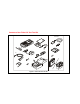
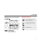
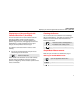
For low frequency measurements and high signal
levels, use the Black COM (Common) Input as single
ground. Figure 3 shows this.
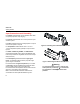
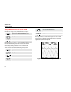
For measurements at higher frequencies up to 10 MHz
or low levels, use both Shielded Test Leads with Short
Ground Leads instead of using the COM Input.
For measurements at frequencies above 10 MHz use the
VP40 10:1 probe with a short ground lead.
Bear in mind that the Short Ground Leads must be
connected to the same potential! Refer to Figure 4.
Figure 3. Grounding with Unshielded Ground Lead.
Figure 4. Grounding with Short Ground Leads
Warning
To avoid electrical shock or fire, use only one
COM (common) connection
, or ensure that
all connections to COM are at the same
potential.