
Application Note

Application Note
From the Fluke Digital Library @ www.fluke.com/library
Power interruptions
Unfortunately the unconditional
availability of electrical power
can never be taken for granted.
In fact, quite frequently interrup-
tions occur of various durations.
Many of these pass unnoticed,
but some may prevent your
equipment from working prop-
erly. The longest interrupts are
obviously the ones that make all
lights go down and all equip-
ment stop. But sometimes, we
see only a single piece of equip-
ment blink as if the power has
been interrupted, after which
operation continues immediately
with nothing else apparently
indicating that anything has
happened. This then raises ques-
tion of whether the ‘hiccough’
was due to a power malfunction,
or to the fact that the affected
piece of equipment itself is
faulty.
An oscilloscope from the
ScopeMeter 190 Series II can
be a valuable tool in finding
answers here, as it allows you
to detect these short-duration
interrupts of the electrical power
system.
Pulse width triggering
ScopeMeter 190 Series II oscil-
loscopes are equipped with a
pulsewidth-trigger mode. This
trigger mode is able to detect,
for instance, the pulse width in
Electrical energy is the driving force of today’s world. It
is available almost everywhere you go, and is capable
of driving all sorts of equipment from heating and cook-
ing equipment, through motors and ventilators to the PC
that this application note is written on. And it’s available
all the time. Or is it?
a repetitive signal. But it is also
capable of detecting the absence
of a signal for a certain amount
of time, for instance of the mains
voltage.
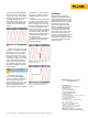
When the oscilloscope is used
to monitor the mains signal,
an interruption will trigger the
oscilloscope and the waveform
information will be “frozen” in
the oscilloscope’s memory. If
more such events should occur,
the scope screen will automati-
cally be updated for each such
event, and the successive events
will be stored in the REPLAY-
memory. The whole sequence
of events can then be re-played
and analyzed from the scope
screen which also displays a
date- and timestamp. The replay
screens can be copied to a PC for
documenting and archiving.
Here’s a set-up that allows
you to detect the moments that
the mains voltage is interrupted.
Instrument set-up
The mains voltage is a sinusoidal
ac voltage. This means that it is
half the time positive and half
the time negative. A full cycle
takes 20 ms if the line frequency
is 50 Hz, or 16.6 ms for 60 Hz
systems.
Given this ac voltage, we can
set-up the ScopeMeter to detect
if the mains voltage is inter-
rupted. To do so, we set up the
ScopeMeter to recognize the
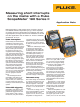
Measuring short interrupts
on the mains with a Fluke
ScopeMeter
®
190 Series II
absence of any voltage for longer
than ¾ of a cycle, this is 15 ms
(or 12.5 ms for a 60 Hz system),
as this can only happen during
an interrupt of the normal cycle.
Connect the ScopeMeter
probe to input A, and connect
the probe ground clip (alligator)
to the mains neutral. Connect
the probe tip to the ‘live’ mains
line. Be careful in making these
connections as the mains system
carries hazardous voltage! Use
only the safety-designed acces-
sories described with the Fluke
ScopeMeter.
Alternatively, if a low-voltage
transformer is part of the system
under test, measure on the low-
voltage side of that transformer
as this provides the necessary
safety barrier.
Select the ScopeMeter to work
in ‘Scope’ mode, and make sure
the instrument is in ‘Auto’ mode
(see upper right corner of the
screen). If it is not in ‘Auto’ mode,