
Application Note

2 Fluke Corporation Measuring short interrupts on the mains with a ScopeMeter
®
190 Series II
press the green AUTO/MANUAL
button to set the indicator in the
upper-right corner to read ‘Auto’.
A continuous sinewave will now
be visible. Change the time-
base setting to give about 2 or
3 cycles per horizontal division,
so select 20 or 40 ms/div (see
figure 1).
Change the horizontal trigger
position to a position to the right
of the screen, e.g. at a position
three divisions from the right
side of the screen. Look at the
∫-symbol in Figure 1. A continu-
ous sinewave will remain visible
and is repeatedly refreshed on
screen. The vertical position of
the ∫-symbol marks the voltage
level that the trigger system is
responding to.
Now select the ‘Trigger’
menu, and press F4 (Trigger
options) and select “Pulse Width
on A” from the menu. Press
Enter. You will notice that a new
menu layer appears. Select the
negative oriented pulses (‘U’-
shaped pulses) and the condition
‘Pulsewidth >t ’, select ‘Update
on trigger’ in order to catch suc-
cessive interrupts rather than
only one.
Press Enter until all selections
are made, and the menu text is
switched off again. The up and
down controls (s and t) can now
be used to change the time dura-
tion of the interrupts that the
scope will respond to. Set this to
15 ms (or 12.5 ms when working
on a 60 Hz system). The oscil-
loscope is now ready to respond
to any short-term interrupt of
the mains voltage.
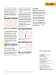
Figures 3 and 4 provide some
examples of power interrupts
that were captured.
Conclusion
Malfunctioning of electronic
equipment is sometimes related
to short-duration interrupts of the
mains supply. This calls for a tool
to find such interrupts, complete
with date and time of occur-
rence. Fluke ScopeMeter 190
Series II oscilloscopes are capa-
ble of conveniently detecting
and storing such power inter-
rupts. Even if many such events
occur over a longer period of
time, up to 100 individual events
can be stored, complete with
date- and time-indicator, making
longer-term power monitoring
easier than ever.
Fluke Corporation
PO Box 9090, Everett, WA 98206 U.S.A.
Fluke Europe B.V.
PO Box 1186, 5602 BD
Eindhoven, The Netherlands
For more information call:
In the U.S.A. (800) 443-5853 or
Fax (425) 446-5116
In Europe/M-East/Africa +31 (0) 40 2675 200 or
Fax +31 (0) 40 2675 222
In Canada (800)-36-FLUKE or
Fax (905) 890-6866
From other countries +1 (425) 446-5500 or
Fax +1 (425) 446-5116
Web access: http://www.fluke.com
©2005-2011 Fluke Corporation.
Specifications subject to change without notice.
Printed in U.S.A. 4/2011 2543312B A-EN-N
Pub_ID: 10616-eng, rev 01
Modification of this document is not permitted
without written permission from Fluke Corporation.
Fluke. Keeping your world
up and running.
Figure 1: 60 Hz mains voltage using AUTO-
mode.
Figure 2: Menu layer for pulse-width trigger
settings.
Figure 3: Power disruption due to a loose
contact in the wiring.
Figure 4: Interrupt as stored in the replay-
memory. Note the date- and time-markers
that were automatically attached to the
recording.