® 150X Series Insulation Testers Calibration Manual PN 2465477 November 2005, Rev. 1, 7/07 © 2005, 2007 Fluke Corporation, All rights reserved. Printed in USA All product names are trademarks of their respective companies.
LIMITED WARRANTY AND LIMITATION OF LIABILITY Each Fluke product is warranted to be free from defects in material and workmanship under normal use and service. The warranty period is one year and begins on the date of shipment. Parts, product repairs, and services are warranted for 90 days.
Table of Contents Title Introduction........................................................................................................ Safety Information ............................................................................................. Contacting Fluke................................................................................................ General Specifications ....................................................................................... Electrical Specifications .......
150X Series Calibration Manual Discharge Circuit Test ................................................................................... Testing the Insulation Function ..................................................................... Insulation Resistance Accuracy Tests ....................................................... Insulation Function, External Sense.......................................................... Source Voltage Accuracy Test, "R" Nominal ..........................................
List of Tables Table 1. 2. 3. 4. 5. 6. 7. 8. 9. 10. 11. 12. 13. 14. Title Symbols.................................................................................................................. Required Performance Test Equipment ................................................................. Required Calibration Adjustment Equipment ........................................................ Voltage Accuracy Tests .........................................................................................
150X Series Calibration Manual iv
List of Figures Figure 1. 2. 3. 4. 5. 6. 7. Title Replacing the Fuse and Batteries ........................................................................... Display Test ........................................................................................................... Disassembling the Meter........................................................................................ Insulation Terminal Clips.......................................................................................
150X Series Calibration Manual vi
Introduction The Fluke Models 1503, 1507, and 1508 are battery-powered insulation testers (hereafter, Tester or UUT). These Testers meet CAT IV IEC 61010 standards. The IEC 61010 standard defines four measurement categories (CAT I to IV) based on the magnitude of danger from transient impulses. CAT IV Testers protect against transients from the primary supply level (overhead or underground utility service).
150X Series Calibration Manual • Comply with local and national safety requirements when working in hazardous locations. • Use proper protective equipment, as required by local or national authorities when working in hazardous areas. • Avoid working alone. • Use only the replacement fuse specified or the protection may be impaired. • Check the test leads for continuity before use. Do not use if the readings are high or noisy. Table 1.
Insulation Testers General Specifications General Specifications Maximum Voltage Applied to any Terminal ... 600 V ac rms or dc Storage Temperature........................................ −40 °C to 60 °C (−40 °F to 140 °F) Operating Temperature .................................... −20 °C to 55 °C (−4 °F to 131 °F) Temperature Coefficient .................................. 0.05 x (specified accuracy) per °C for temperatures < 18 °C or > 28 °C (< 64 °F or > 82 °F) Relative Humidity...........................
150X Series Calibration Manual Electrical Specifications AC/DC Voltage Measurement Accuracy Range Resolution 50 Hz to 400 Hz ± (% of Rdg + Digits) 600.0 V 0.1 V + (2 % + 3) Input Impedance ............................................... 3 MΩ (nominal), <100 pF Common Mode Rejection Ratio (1 kΩ unbalanced) .............................................. > 60 dB at dc, 50 or 60 Hz Overload Protection .........................................
Insulation Testers Electrical Specifications Model 1503 Output Voltage 500 V (0 % to + 20 %) 1000 V (0 % to + 20 %) Display Range Resolution 0.01 to 20.00 MΩ 0.01 MΩ 20.0 to 200.0 MΩ 0.1 MΩ 200 to 500 MΩ 1 MΩ 0.1 to 200.0 MΩ 0.1 MΩ 200 to 2000 MΩ 1 MΩ Test Current Accuracy ± (% of Rdg + Digits) 1 mA @ 500 kΩ ± (2.0 % + 5) 1 mA @ 1 MΩ ± (2.0 % + 5) EN61557 Specification (Models 1503 and 1507) The following tables are a requirement for European labeling.
150X Series Calibration Manual The following tables can be used to determine the maximum or minimum display values considering maximum instrument operating error per EN61557-1, 5.2.4. Insulation Resistance Maximum and Minimum Display Values (Models 1503 and 1507) 50 V 6 100 V 250 V 500 V 1000 V Limit Value Minimum Display Value Limit Value Minimum Display Value Limit Value Minimum Display Value Limit Value Minimum Display Value 0.05 0.06 0.07 0.08 0.05 0.06 0.07 0.08 0.05 0.06 0.07 0.
Insulation Testers Basic Maintenance Earth-Bond Resistance Maximum Display Values (Models 1503 and 1507) Limit Value Maximum Display Value Limit Value Maximum Display Value Limit Value 0.4 0.28 7.0 4.9 100.0 70.0 0.5 0.6 0.7 0.8 0.9 0.35 0.42 0.49 0.56 0.63 8.0 9.0 10.0 20.0 30.0 5.6 6.3 7.0 14.0 21.0 200.0 300.0 400.0 500.0 600.0 140.0 210.0 280.0 350.0 420.0 1.0 2.0 3.0 4.0 5.0 6.0 0.7 1.4 2.1 2.8 3.5 4.2 40.0 50.0 60.0 70.0 80.0 90.0 28.0 35.0 42.0 49.0 56.0 63.0 700.0 800.0 900.
150X Series Calibration Manual XWWarning To avoid shock, injury, or damage to the Tester: • To avoid false readings, which could lead to possible electric shock or personal injury, replace the batteries as soon as the battery indicator (B) appears. • Use ONLY fuses with the amperage, interrupt, voltage, and speed ratings specified. • Turn the rotary switch to OFF and remove the test leads from the terminals. 1. Remove the yellow boot from the Tester.
Insulation Testers Disassembling and Reassembling the Tester Testing the Display Press and hold the blue key, and simultaneously turn the UUT on. Compare the display with the example in Figure 2. Check all segments for clarity and contrast. bbw01f.eps Figure 2. Display Test Backlight Test The display backlight is a toggle function controlled by the H key. Each press of Hcauses the backlight to change states, on to off or off to on. To test the backlight: 1.
150X Series Calibration Manual Holster PCA Screws Fuse PCA Battery Door Light-dispersing Back Panel Glass LCD Display Case Screws Elastomeric Strip Plastic Shields Red Gray Plastic Bezel Keypad Black Case Bottom Case Top ecz20f.eps Figure 3. Disassembling the Tester Removing the Holster The standard Tester comes equipped with a snug-fitting yellow rubber holster. The holster helps protect the Tester from rough handling and normally remains on the Tester.
Insulation Testers Disassembling and Reassembling the Tester Removing the Battery Door XWWarning To avoid the risk of electrical shock, turn the rotary switch to OFF, and remove the test leads from the front-panel terminals before removing the battery cover. With the boot removed, the next step in disassembling the Tester is to remove the battery door. Use the following procedure to remove the door: 1. Locate the black slotted lock on the lower rear of the Tester. 2.
150X Series Calibration Manual eca18f.eps Figure 4. Insulation Terminal Clips 3. With one hand over the PCA, roll the top case over (face up) and lift it away from the PCA. Note Two red and one black plastic shields are used to isolate the user from the input terminals. With the PCA removed, these shields are loose and can fall away from the PCA. 4. Remove and set aside all three shields for use during reassembly.
Insulation Testers Disassembling and Reassembling the Tester 3. Locate the gray plastic tab just above and to the left of the hole. Using your thumbnail, press the tab down and toward the display end of the PCA. This will release the LCD assembly from the PCA. WCaution To avoid damaging the plastic guide pins on the LCD assembly, keep the LCD assembly parallel to the PCA when separating the two parts. 4. Without tilting the PCA, lift it straight up and away from the LCD assembly. 5.
150X Series Calibration Manual 3. Remove the old glass LCD display from the bezel. Note Make sure the new LCD display is clean (free of lint and fingerprints) before placing it in position in the bezel. 4. Position the new glass LCD display in the bezel; the silver face should face the rear, and the stepped portion of the glass should be directly under the elastomeric slot on the bezel. 5. Drop the elastomeric strip into its slot on the bezel. 6.
Insulation Testers Required Tools and Equipment Required Tools and Equipment Tables 2 and 3 list the required equipment used in the Performance Test and Calibration Adjustments. If a recommended model is unavailable, use a substitute with equivalent or better specifications. Table 2. Required Performance Test Equipment Equipment Calibrator Required Characteristics Recommended Model AC Voltage Range: 0 – 600 V Accuracy: ± 0.
150X Series Calibration Manual Performance Tests The following series of tests comprise a performance test for verifying the accuracy of the Tester (UUT) and its performance level. The performance test is recommended as an acceptance test for incoming inspection and as a calibration procedure for periodically ensuring the accuracy of the Tester. Fluke recommends running the performance test at least once a year.
Insulation Testers Performance Tests Discharge Circuit Test The following Discharge Circuit Test is a safety related test that verifies input jack wiring to the PCA, the RSOB contacts, RSOB PCA pads, and other active discharge components on the PCA. 1. Place a Shorting Bar across the UUT COM and INSULATION input terminals. 2. Set the UUT rotary switch to 1000 V, and press T. 3. Release the T key and remove the short from the UUT input terminals.
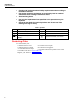
150X Series Calibration Manual Table 5. Insulation Resistance Accuracy Test Display Reading Limits Insulation Voltage Range Applied 1 1000 V 2 Step Display Units 1503 1507/1508 9 GΩ N/A 7.8 to 10.2 1000 V 1.9 GΩ 1862 to 1938 N/A 3 1000 V 1 MΩ 0.5 to 1.5 0.5 to 1.5 4 1000 V 49 MΩ 47.5 to 50.5 47.8 to 50.2 5 1000 V 60 MΩ 58.3 to 61.7 58.6 to 61.4 6 500 V 500 kΩ 0.44 to 0.56 0.44 to 0.56 7 250 V 250 kΩ N/A 0.20 to 0.30 8 100 V 100 kΩ N/A 0.6 to 0.
Insulation Testers Performance Tests Table 6.
150X Series Calibration Manual I Nominal Test The following test verifies the UUT’s ability to maintain the nominal insulation test current while loaded. 1. Connect the Fluke 5320A high resistance output terminals to the UUT INSULATION and COM terminals. 2. Set the 5320A to the high resistance source function (H). 3. Set the 5320A for the Applied Load called out in Table 8 for Steps 1-5. 4. Press T and verify that the Fluke 5320A current reading is > 1000.0 μA for steps 1-5. Table 8.
Insulation Testers Performance Tests 5. Press T, and verify that the UUT reading is within the display reading limits shown in Table 9. 6. Connect the Fluke 5320A high resistance output terminals to the UUT COM and Ω terminals. 7. Set the Fluke 5320A to the high resistance source function (H). 8. Press T, and verify that the reading is within the display reading limits for Table 9, Step 4. Table 9.
150X Series Calibration Manual Calibration Adjustment The Tester features closed-case calibration adjustment using known reference sources. The Tester measures the applied reference source, calculates correction factors and stores the correction factors in nonvolatile memory. The following sections present the features and Tester function keys that are used during the calibration adjustment procedure.
Insulation Testers Calibration Adjustment Restoring the Default Password If you forget the calibration password, the default password (1234) can be restored using the following steps. XWWarning To avoid electrical shock or personal injury, remove the test leads and any input signal before removing the Tester's bottom case. 1. Remove the back case from the UUT. Leave the PCA in the top case. 2. Apply 6.0 V across the battery contact pads (J8) + and − on the PCA. See Figure 6. 3.
150X Series Calibration Manual Keys Used in the Calibration Steps The Tester keys behave as follows when you perform the calibration adjustment procedure: T stores the calibration value and advances to the next step. H ignores the calibration value and advances to the next step. This key is also used to exit the calibration function after the calibration adjustment sequence is complete. Calibration Adjustment Procedure Use the following steps to make calibration adjustments to the Tester.
Insulation Testers Calibration Adjustment Table 10. Calibration Adjustment Steps Switch Position Input Terminal Adjustment Step Input Value C-01 0m A, 0 Hz C-02 15u A, 0 Hz C-03 0.18 mA, 0 Hz C-04 1.8 mA, 0 Hz C-05 0.5 mA, 0 Hz C-06 5.0 mA, 0 Hz C-07 0.5 mA, 0 Hz C-08 5.0 mA, 0 Hz C-09 5.0 mA, 0 Hz C-10 300 mA, 0 Hz + : Volts Input C-11 25.0 V, 0 Hz − : COM C-12 750 V, 0 Hz + : Continuity Input C-13 0.5 V, 0 Hz − : COM C-14 5.
150X Series Calibration Manual Service and Parts User service is limited to replacing parts. Table 11 identifies the replacement parts used by all models, Tables 12, 13, and 14 identify the replacement parts unique to each model. Figure 7 shows the location of each part. To order replacement parts refer to Contacting Fluke earlier in this manual. MP32 MP18 H30-32 (3x) F1 MP16 MP7 MP21 MP34 MP40-43 (4x) MP10 H26-29 (4x) MP11 MP12-13 (2x) MP9 MP15 MP19 MP1 MP20 MP22-24 (3x) MP6 ecz19f.
Insulation Testers Service and Parts Table 11.
150X Series Calibration Manual Table 12.