
User's Manual


Calibration Adjustment
Final Calibration (Firmware: V10.9 and Lower) 5
5-39
7. Press
F2
to select the next calibration step, set the 5502A to the next
calibration point, and start the calibration. Continue through all calibration
points of Table 5-18.
8. Set the 5502A to Standby and continue at the Input ABCD (AB) Zero section.
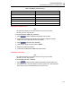
Table 5-18. Input ABCD Gain Calibration Points
Cal step UUT input value (5502A NORMAL)
CL 0799 5 mV
CL 0800 12.5 mV
CL 0801 25 mV
CL 0802 50 mV
CL 0803 125 mV
CL 0804 250 mV
CL 0805 500 mV
CL 0806 1.25 V
CL 0807 2.5 V
CL 0808 5 V
CL 0809 12.5 V
CL 0810 25 V
CL 0811 50 V (set 5502A to OPR!)
CL 0812 125 V
CL 0813 250 V
Input ABCD (AB) Zero
To do the Input ABCD (AB) Zero calibration:
1. Press
F2
to select calibration adjustment step CL 0852.
2. Short circuit Input A, B, C, D (A, B) with 50 Ω feed through terminations.
3. Press
F3
to start the zero calibration.
4. Wait until the display shows the status :READY.
5. Remove the input terminations.
6. For Fluke 190-062, 190-102, and 190-202: continue at the Multimeter (DMM)
Volt Gain section. For Fluke 190-104 and 190-204: continue at the Save
Calibration Data and Exit section.