
User's Manual


Disassembly
Disassembly and Reassembly Procedures 6
6-5
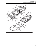
How to Access the Top Side of PCA
Most of the measurement points are located on the top side of the PCA. For access to
this side, remove the upper plate (shielding lid):
1. Remove the four screws M3x6.5 (total length) with a spring-washer (left side, right
side, and bottom side).
2. Remove the four screws M3x10 (total length) that are grouped in a square around
the sampling chip N2000.
3. Observe how the screening plate fits onto the lower chassis before you remove this
plate to access the top side of the PCA.
How to Access the Bottom Side of PCA
To avoid contaminating the flex cable contacts with grease from your fingers, do not
touch these contacts or wear cotton gloves. Contaminated contacts may not cause
immediate instrument failure. Failures typically show up when contaminated instruments
are operated in humid areas.
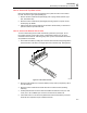
1. Unlock both flat cables by shifting the connector latch at the left and right edge with a
small screwdriver. The latch is an integral part of the connector body. See Figure 6-1.
st8682.eps
Figure 6-1. Flat Cable Connector
2. Remove the flat cables from connector X9303 (to LCD), J9414 (to keyboard), J9415
(to LCD backlight).
3. Remove the four screws M3x10 that fix the PCA to the lower chassis (shielding
assembly).
4. Carefully slide the PCA out of the holes for the BNCs and Banana Jacks (2-ch Test
Tools). The A, B, and Meter input circuits are covered with an isolation foil.
5. Take careful notice on how the foil is positioned around the PCA before you remove
the foil as far as required to repair a defective channel.