
User's Manual


Fluke 190-062, -102, -104, -202, -204, -502, -504
Service Manual
4-8
10. Press
F2
.
The test pattern is removed and the Test Tool shows
Contrast (CL 0110):
11. Press
F2
again to do the next step Contrast (CL 0120):
12. Press
F3
(CALIBRATE).
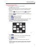
The Test Tool shows a light display. The test pattern shown in Figure 4-2
may not be visible or hardly visible.
Observe the display closely and verify that the display shows no
abnormalities.
13. Turn off and turn on the Test Tool to exit the calibration menu and return to
the normal operating mode.
If the maximum, minimum, or default display contrast is not OK, then you can
adjust these items without performing a complete calibration adjustment; refer to
Section 5 for detailed information.
Scope Input A, B, C, D Tests
Input A, B, C, D Vertical Accuracy Test
Warning
To prevent possible electrical shock, fire, or personal injury,
ensure that the calibrator is in standby mode before making any
connection between the calibrator and the Test Tool.
Dangerous voltages are present on the calibration source and
connection cables during these steps.
Note
The test steps for channels C and D are only for the models
190-104, 190-204, or 190-504.
Proceed as follows:
1. Connect the Test Tool to the 5502A as shown in Figure 4-3. The vertical
channels A, B, C, and D are checked in succession so that there is one
waveform on the display at a time to facilitate amplitude adjustment.