
Product Manual


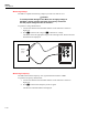
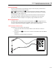


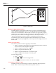
Table Of Contents
- 8808A Users Manual
- 1. Introduction and Specifications
- 2. Preparing the Meter for Operation
- 3. Operating the Meter from the Front Panel
- Introduction
- Dual Display
- Rear Panel
- Adjusting Meter Range
- Selecting a Measurement Rate
- Selecting a Measurement Function
- Compare Function (COMP)
- List and Number Editors
- Function Keys S1 – S6
- Power-Up Configuration
- Calibration
- 4. Operating the Meter Using the Computer Interface
- Introduction
- Preparing the Meter for Operations via the RS-232 Interface
- Getting Started with an Installation Test
- How the Meter Processes Input
- How the Meter Processes Output
- Triggering Output
- Status Registers
- Computer Interface Command Set
- Common Commands
- Function Commands and Queries
- Function Modifier Commands and Queries
- Range and Measurement Rate Commands and Queries
- Measurement Queries
- Compare Commands and Queries
- Trigger Configuration Commands
- Miscellaneous Commands and Queries
- RS-232 Remote / Local Configurations
- RS-232 Save / Recall System Configurations
- Sample Program Using the RS-232 Computer Interface
- Appendices
Operating the Meter from the Front Panel
Selecting a Measurement Function 3
3-15
Diode / Continuity Testing
Press G to toggle between the continuity and diode test functions for the primary
display. (These functions cannot be selected for the secondary display.)
To perform a continuity test:
1. If required, press G to select the continuity test function.
2. Connect the test leads between the Meter and the circuit under test as shown in
Figure 3-10.
The beeper emits a continuous tone if the input is below 20 Ω.
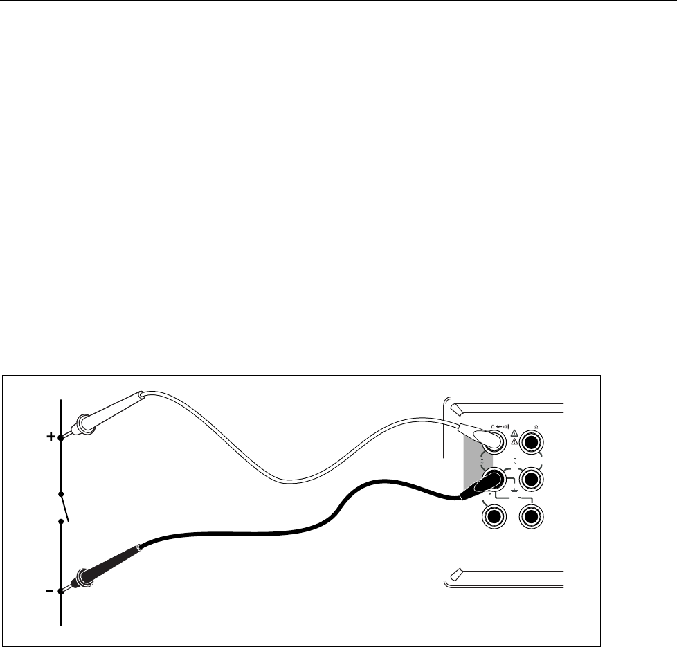
To perform a diode or transistor junction test:
1. If required, press G to select the diode test function.
2. Connect the test leads between the Meter and the diode or transistor junction as
shown in Figure 3-11.
The forward voltage of the semiconductor junction (or junctions) is measured.
Readings are displayed in the 2 V range at the fast measurement rate. The Meter
displays 0L if the input is above +2 V.
HI
LO
1000V
750V
2W/4W
MAX
INPUT SENSE
HI
LO
4W
10 A
mA
200 mA
MAX
10 A
MAX
1000V CAT I
600 V CAT II
500 V pk
V
1V
300V
eue15.eps
Figure 3-10. Continuity Test