
User's Manual


268XA
Service Manual
6-4
especially clean to ensure a strong connection. An oxidized PCA pad causes the
solder to wick up the component lead, leaving little solder on the pad itself.
Error Detection
At power-up, the device software performs self-tests. If any errors in device operation are
detected, they are reported on the device front panel with Error in the primary display and
a decimal error code number in the secondary display. If there is more than one error,
they are displayed sequentially. Selftest errors can be retrieved from RS-232 commands
and the network.
A selftest includes a test of the following items:
• FLASH ROM parameters, communication parameters and calibration constants.
• RAM Device and channel configuration plus RAM images of FLASH ROM
parameters.
• Ethernet Ethernet chip and static Ethernet RAM.
• Display Display processor and display board
• Inguard Specific tests for ROM checksum, RAM, A/D converter, zero offset test,
reference balance test, ohms overload test, and open thermal couple
• Slot configuration check Specific checks are made to determine if the active
module configuration has changed since the device last ran a scan.
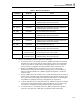
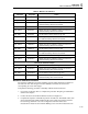
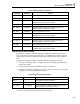
A summary of the possible error codes are shown in Table 6-1, including the front panel
error code (in decimal) and the corresponding network and RS-232 error code (in
hexadecimal). The faults that might cause each error are described in “Troubleshooting
the Device” later in this chapter.