
User's Manual

268XA
Service Manual
2-16
Open Thermocouple Check
Under control of the inguard microprocessor, the open thermocouple check circuit applies
a small ac signal to a thermocouple input before each measurement. If an excessive
resistance is encountered, an open thermocouple input condition is reported.
Analog Input PCA Block Description
The following paragraphs briefly describe the major sections of the Input Connector
PCA, which is the “Universal Input Module” used for connecting the analog inputs to the
instrument.
20-Channel Terminals
Twenty HI and LO terminal blocks are provided in two rows, one for channels 1 through
10 and one for channels 11 through 20. The terminals can accommodate a wide range of
wire sizes, starting with 12 gauge as the largest size. The two rows of terminal blocks are
maintained very close to the same temperature for accurate thermocouple measurements.
Reference Junction Temperature
A semiconductor junction is used to sense the temperature of the thermocouple input
terminals. The resulting dc output voltage is proportional to the block temperature and is
sent to the A/D Converter PCA for measurement.
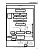
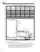
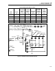
A/D Converter PCA Circuit Description
The following paragraphs describe the operation of the circuits on the A3 A/D Converter
PCA. See Figure 2-5 for a block diagram. The PAI and FAI A/D Converter PCAs are
identical, except for physical signal switching, and both use the following:
• Motorola 68302 microprocessor.
• Flash ROM
• RAM
• Serial Interface to the Main Board.
• A Fluke manufactured Stallion IC (U30) for range selection and frequency
measurements.
• Multi-Slope A/D converter comprised of discrete components and an FPGA (Field
Programmable Gate Array) (U18).
The difference between the A/D boards is that the PAI uses reed relays, while the FAI
uses optically coupled solid state relays.