
User's Manual

Theory of Operation
A/D Theory of Operations
2
2-25
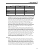
Table 2-7. Analog/Digital Converter Measurement Cycle
State Counts Time
Autozero 125 200.0 µs
Integrate 307 491.4 µs
Deintegrate1 64 102.4 µs
Deintegrate2 24 38.4 µs
Overhead n/a 1.333 µs
Total 833.533 µs
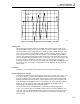
Integrate
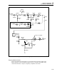
The integrate state is when the input voltage is actually connected to the integrator. PREF
and NREF are each switched off and on 10 to 20 times during this state and DREF is still
off, INT is on, AZ is off, and the CMP signal is switching off and on. The primary signal
is pin 7 of A3U19, which looks approximately like a triangular wave with 51.2 µs slope
when the input voltage is zero. The triangular wave is very irregular at other voltages,
moving on an upward or downward slope and reversing direction within the integrate
time period. The actual behavior is determined by the algorithm in the FPGA.
This tests the CMP signal at defined times spaced 51.2 µs apart. If the CMP signal is
turned off, then NREF is turned on. PREF and NREF are never on at the same time
during integrate. First, the existing reference is turned off and a 1-count (1.6 us) period is
entered where only the input signal is integrated. Next, a reference of a polarity such as to
keep the total number of NREF pulses so far equal to the number of PREF pulses is
turned on for 1-count (1.6 µs).
Finally, the reference with a polarity determined by the comparator (CMP) test at the
very first of the interval is turned on for the remaining 30 counts (48 µs) of the interval.
The beginning first interval is only 16 counts instead of 32 counts. The last state is 35
counts to allow for completing the PREF and NREF pulse count equalization. There are 8
normal intervals of 32 counts. The purpose is to bound the waveform to prevent amplifier
saturation, prevent charge injection from being a variable with waveform changes and
prevent logic signals themselves from injecting unwanted signals into the summing node.
The integrate state is the primary measuring interval, and during this time the FPGA
accumulates counts of how long PREF and NREF have been applied. The count is
completed during deintegrate. Typical integrator output waveforms for different inputs
are shown in Figure 2-9, Figure 2-10, and Figure 2-11.
Deintegrate1
Deintegrate1 is when the remaining charge of the capacitor is removed and the major
count is completed. The input is turned off and no longer affects the reading. INT is off,
PREF, and NREF continue to switch a few more times, and the signal is brought very
close to zero. The previous integrate state ended in a hold (both references off) and this
state begins with the PREF signal on. The comparator is examined after each count and
as soon as CMP goes low, a hold state begins with both references off. Depending of the
level of the signal at the beginning of deintegrate, this can result in PREF being on from 1
to 60 counts. At the end of the hold count NREF, is turned on until CMP drops low.