® 1621 Earth Ground Tester Users Manual PN 2842206 June 2007 © 2007 Fluke Corporation, All rights reserved. Printed in the Netherlands. All product names are trademarks of their respective companies.
LIMITED WARRANTY AND LIMITATION OF LIABILITY Each Fluke product is warranted to be free from defects in material and workmanship under normal use and service. The warranty period is two years and begins on the date of shipment. Parts, product repairs, and services are warranted for 90 days.
Table of Contents Title Introduction .......................................................................................... Unpacking............................................................................................. Packing ................................................................................................. Safety Regulations ................................................................................ Symbols ..................................................................
1621 Users Manual ii
List of Tables Table 1. 2. 3. 4. Title Optional Accessories ............................................................................ Features and Functions ......................................................................... Display.................................................................................................. Troubleshooting....................................................................................
1621 Users Manual iv
List of Figures Figure 1. 2. 3. 4. 5. Title Features and Functions ......................................................................... Display.................................................................................................. Battery Installation................................................................................ Three-Pole Measurement Setup ............................................................ AC Resistance Measurement ..............................................
1621 Users Manual vi
1621 Earth Ground Tester Introduction The Fluke 1621 Earth Ground Tester (referred throughout as the “Tester”) is an easy to use instrument for measuring the resistance to earth ground of a specified earth ground electrode. The Tester can perform a 3-pole fall-ofpotential test conforming to IEC/EN 61557-5. The Tester can also perform ac resistance testing.
1621 Users Manual Safety Regulations This measuring device is only to be installed and operated by qualified personnel in compliance with the safety precautions and regulations that follow. Additionally, the use of this equipment requires compliance with all legal and safety regulations pertaining to each specific application. Similar regulations apply to the use of accessories.
Earth Ground Tester Symbols • Do not open the battery compartment when leads are connected. • While a measurement is in progress, do not touch the earth electrode, auxiliary electrode or probe. Symbols The following symbols are found on the Tester or in this manual. X Hazardous voltage. Voltage >30 V dc or ac peak might be present. W Risk of danger. Important information. See Users Manual.
1621 Users Manual Accessories The following accessories are shipped with your 1621 Earth Ground Tester: • Users manual • Two measuring leads with alligator clips, 2 m (6 ft) • One battery, 9 V alkaline (LR61) • One protective holster, yellow • One CD-ROM For a list of optional accessories, see Table 1. To order an accessory, see “Service.” Table 1. Optional Accessories Description 4 Item/Part No.
Earth Ground Tester Features Features Refer to Figure 1 and Table 2 for Tester features and functions. 1 2 3 4 ! 10 5 9 6 7 8 evp01.eps Figure 1.
1621 Users Manual Table 2. Features and Functions No.
Earth Ground Tester Features Software To check the software version, set the rotary switch to OFF, and then press and hold START and set the rotary switch to any On position (3 pole, 2 pole or LIMIT). The software version displays. LCD Display The Tester features a lighted LCD display that shows measurement readings, messages and icons. Refer to Figure 2 and Table 3 for descriptions of the display’s icons. To turn on the display light, press and hold DISPLAY for 2 seconds.
21 Users Manual Table 3. Display No.
Earth Ground Tester Features Resistance Limit Mode The Tester has a resistance limit mode that allows you to set a maximum resistance reading. If a resistance reading exceeds the set limit, the Tester beeps and the >LIMIT icon displays. The limit can be set between 0 and 1999 Ω. To set the maximum resistance: 1. Set the rotary switch to LIMIT. If the limit mode is on, the Tester displays the stored limit setting. If the limit mode is off, the Tester displays OFF. 2.
1621 Users Manual Battery Installation The Tester is shipped with a 9 V alkaline (LR61) battery, which you will need to install. When the battery voltage is low, the LO-BAT icon displays, and you will need to replace the battery. To install or replace the battery: 1. Set the rotary switch to OFF, disconnect all test leads, and remove the Tester from its holster. 2. On the back of the Tester, use a small screwdriver to gently pry open the battery cover.
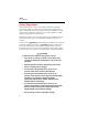
Earth Ground Tester Operating Instructions Operating Instructions XW Warning To avoid possible electric shock or personal injury, before powering up and operating the device, carefully read and follow all safety regulations described in “Safety Regulations.” 3-Pole Measurement To perform a 3-pole measurement: 1. Insert the probe and auxiliary electrode stakes into the soil as shown in Figure 4. Ensure the probe stake is a minimum distance of 20 m (64 ft) from the earth ground electrode.
1621 Users Manual RH RS RE Earth Electrode Probe >20 M (64 FT) Aux. Earth Electrode >20 M (64 FT) evp03.eps Figure 4.
Earth Ground Tester Operating Instructions AC Resistance Measurement To perform an ac resistance measurement: 1. Set the rotary switch to OFF. 2. Plug a test lead into jack H/C2 and a test lead into jack E/C1. See Figure 5. 3. Connect the test leads to each end of the conductor under test. See Figure 5. 4. Set the rotary switch to 2 pole and press START. The ACTIVE icon displays to indicate that the measurement is in progress.
1621 Users Manual Troubleshooting To troubleshoot your Tester, follow the steps in Table 4. Table 4. Troubleshooting Step Description 1 Auxiliary electrode resistance (RH) too high If the auxiliary electrode resistance is too high (exceeds 199 ke), it is not possible to drive the current necessary for reliable measurements. The measurement is blocked and the >LIMIT icon displays.
Earth Ground Tester Specifications Specifications Note Fluke reserves the right to modify specifications without notice for the purpose of product improvement. Measuring functions: 3-pole earth ground resistance, 2 pole AC resistance of a conductor Interference voltage Intrinsic error: Refers to the reference temperature range and is guaranteed for 1 year Measuring rate: 2 measurements / second Battery condition: LO-BAT is displayed if voltage drops below 6.
1621 Users Manual Temperature Coefficient: ± 0.1 % of range per degree Kelvin Safety: IEC/EN 61010-1, 600VCATII, pollution degree 2 Maximum Deviations: Parameter Deviation influence Influence Factor E1 Position 0% E2 Supply Voltage 0% E3 Temperature E3 2.3 % E4 Serial Interference Voltage (20 V) 0.6 % E5 Probe- and Auxiliary probe Resistance 10 % Test voltage: 3.
Earth Ground Tester Specifications Measuring Range Resolution Display Range 0.15 to 20 Ω 0.01 Ω 0 to 19.99 Ω 200 Ω 0.1 Ω 20 to 199.9 Ω 2 kΩ 1Ω 200 to 1999 Ω Intrinsic Uncertainty ± (6 % of measured value + 5D) Operating Uncertainty IEC 61557* ± (18 % of measured value + 5D) *Covers all deviations caused by influence quantities E1-E5 If the deviation E4 caused by high probe or auxiliary probe resistance is higher than specified W flashes.
1621 Users Manual Automatic changeover of resolution: RH Resolution <7 kΩ 0.01 Ω <50 kΩ 0.1 Ω >50 kΩ 1Ω Interference Voltage Display DC + AC Vmax: 30 Veff Common mode rejection: >80 dB at 50 Hz and 60 Hz Ri: 680 kΩ Measuring uncertainty: <10 % for pure ac and dc signals Storage If the Tester is not going to be used or is being stored for a long period, remove the battery and store separately from the Tester to avoid damage from battery leakage.