P3800 Series High Pressure Hydraulic Deadweight Tester Users Manual PN 3952319 November 2010 © 2010 Fluke Corporation. All rights reserved. Printed in USA. Specifications are subject to change without notice. All product names are trademarks of their respective companies.
LIMITED WARRANTY AND LIMITATION OF LIABILITY Each Fluke product is warranted to be free from defects in material and workmanship under normal use and service. The warranty period is one year and begins on the date of shipment. Parts, product repairs, and services are warranted for 90 days.
Table of Contents Chapter 1 Title General Information ............................................................................ 1-1 Introduction........................................................................................................ How to Contact Fluke ........................................................................................ Safety Information ............................................................................................. Symbols Used in this Manual ......
P3800 Series Users Manual Temperature and Gravity Corrections ...............................................................
List of Tables Table 1-1. Title Page Symbols..................................................................................................................
P3800 Series Users Manual iv
List of Figures Figure 1-1. 3-1. 3-2. 3-3. 3-4. 3-5. 3-6. 3-7. 3-8. 4-1. 6-1. 6-2. Title Hydraulic Circuit Schematic .................................................................................. Pressure Connection - Method 1 ............................................................................ Pressure Connection - Method 2 ............................................................................ Remove Trapped Air............................................................................
P3800 Series Users Manual vi
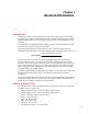
Chapter 1 General Information Introduction This manual contains operation and routine and preventive maintenance instructions for the Model P3830, P3840, and P3860 High Pressure Hydraulic Deadweight Tester (DWT) manufactured by Fluke. This section of the manual provides general information about the DWT. The P3800 Series of Deadweight Testers (DWT) provides a convenient means of testing high pressure instruments for calibration accuracy.
P3800 Series Users Manual Or, visit Fluke's website at www.fluke.com. To register your product, visit http://register.fluke.com. To view, print, or download the latest manual supplement, visit http://us.fluke.com/usen/support/manuals. Safety Information W Warning Pressurized vessels and associated equipment are potentially dangerous. The apparatus described in this manual should be operated by personnel trained in procedures that will assure safety to themselves, to others, and to the equipment.
PISTON/CYLINDER ASSEMBLY HP VALVE Figure 1-1. Hydraulic Circuit Schematic LP VALVE CAPSTAN RAM SCREW ASSEMBLY 7:1 INTENSIFIER TEST STATION TO TAKE ITEM UNDER TEST RELIEF VALVE FLUID RESERVOIR RESERVOIR VALVE Hydraulic Circuit Schematic General Information 1 Hydraulic Circuit Schematic glf01.
P3800 Series Users Manual 1-4
Chapter 2 Preparation Location Note Item number references in the following text, (1), (2), etc, relate to the hydraulic system schematic, shown in the figures below. Place the unit onto a clean, flat surface of a strong and rigid workbench. Ensure that the front of the unit is approximately ¾” / 20 mm from the front edge of the bench to allow the ram screw capstan to overhang and freely rotate.
P3800 Series Users Manual 2-2
Chapter 3 Operation Connections Connect the EUT to the test station using a gauge adapter and lens ring from the selection provided. W Caution This unit can generate very high pressures and, as a consequence, only metal-to-metal sealing is acceptable, i.e. no sealing washers of any description should be used (see Figure 3.1 and 3.2 for methods of sealing). Figure 3-1. Pressure Connection - Method 1 glf02.
P3800 Series Users Manual Figure 3-2. Pressure Connection - Method 2 glf03.eps Procedure for Removing Trapped Air from System Figure 3-3. Remove Trapped Air 3-2 glf04.
Operation Procedure for Removing Trapped Air from System 3 1. Open HP valve (1) and LP valve (2) fully, (counter-clockwise). 2. Open reservoir valve (3), (approximately 4 turns counter-clockwise). 3. Turn capstan fully out (counter-clockwise), and wait for approximately 60 seconds. Figure 3-4. Turn Capstan Fully Clockwise glf05.bmp 4. Turn capstan fully in (clockwise), and wait for approximately 15 seconds. 5. Trapped air from the system will appear as bubbles in the reservoir. 6.
P3800 Series Users Manual Procedure for Priming the Pressure Intensifier Figure 3-5. Prime the Pressure Intensifier glf06.bmp 1. Close LP valve (2) by turning fully clockwise. 2. Turn capstan in (clockwise) until resistance is felt. This is a result of the pressure required to move the intensifier piston backward in its cylinder, and to lift the measuring piston and weight carrier. 3. Some additional bubbles may appear in the reservoir.
Operation Procedure for Generating System Pressure 3 Procedure for Generating System Pressure TEST PORT INTENSIFIER PCU RESERVOIR VALVE (3) HP VALVE (1) LP VALVE (2) CAPSTAN Figure 3-6. Generate System Pressure glf07.eps 1. Close HP valve (1). 2. Open LP valve (2). 3. Turn capstan fully out to prime it with fluid from the reservoir.
P3800 Series Users Manual Figure 3-7. Close Reserve Valve glf08.bmp 4. Close reservoir valve (3). 5. Turn capstan in to generate system pressure. The displaced fluid from the ram screw moves the intensifier piston, generating system pressure to lift the measuring piston and weights.
Operation Generating Calibration Pressure 3 W Caution When reducing pressure ALWAYS use the capstan (by winding out counter-clockwise). NEVER use any of the valves. When reducing from high system pressures, some pressure is still retained in the system, even after winding the capstan fully out (approximately 700 psi / 50 bar). To release this pressure see note below. Note To reduce pressure to zero, wind the capstan fully out anticlockwise. Open HP valve (1) SLOWLY and fully counter-clockwise.
P3800 Series Users Manual 3-8
Chapter 4 Maintenance Introduction The P3800 Series of High Pressure Deadweight Testers have been designed to require minimal maintenance. Routine maintenance entails keeping the unit clean and free from excess oil. The operating fluid should be changed at regular intervals due to potential contamination from items under test. As soon as discoloration of the fluid is observed it should be replaced as soon as possible. W Warning If fluid contacts the skin, a mild allergic reaction may result.
P3800 Series Users Manual PISTON NUT B PISTON PISTON NUT A CYLINDER O RING PISTON COLUMN Figure 4-1. Piston/Cylinder Removal glf10.eps Cleaning 1. Use “non-fluffing”, non-abrasive, lint-free tissue or absorbent cloth. Hold the Piston by the larger “head” end, and rub the tissue back and forth along its length. 2. To remove all traces of contamination, the piston can be cleaned in a suitable solvent. W Caution O-ring seals should not be immersed in solvents, as they will become damaged.
Maintenance Replacement 4 W Caution Never touch the working surface of a clean piston with bare fingers — the natural oil in your skin can cause the piston and cylinder to stick. 5. Wipe excess fluid from the outside surfaces of the cylinder. 6. Roll a NEW tissue into a tapered rod of appropriate size. Force the tissue through the cylinder bore whilst rotating. Ensure that the tissue is a tight fit inside the bore so that dirt and contamination is removed. 7.
P3800 Series Users Manual 4-4
Chapter 5 Recalibration Introduction To maintain the highest accuracy the DWT should be recalibrated at regular intervals. The exact period between recalibrations is dependant on ambient conditions and use. As a general guide, recalibration period should be more than 1 year and less than 3 years. Do's and Don'ts Don'ts • • • • • DO NOT release high pressure using any of the valves — ALWAYS use the Capstan to reduce high pressure before opening any valve.
P3800 Series Users Manual 5-2
Chapter 6 Pressure Corrections Introduction Pressure correction is required for high accuracy work and is due to the effects of pressure on the PCU assembly during operation. By reference to the certificate of calibration provided the actual pressure in the system can be obtained. All values relate to the environmental conditions stated on the certificate. The pressure in the system when the carrier is loaded with major weights can be read directly from the second column of the certificate.
P3800 Series Users Manual Temperature and Gravity Corrections Deadweight testers are manufactured to give an accurate pressure reference at the specified temperature and gravity values indicated on the certificates. The following Standard Values are applied during calibration unless otherwise requested during manufacture (see Certificate). Standard Gravitational acceleration ( G ) 9.
Pressure Corrections Temperature and Gravity Corrections 6 Explanation of Nomogram A straight line passing through the known values of altitude (H) and latitude (L) of the site of the DWT, when extended to scale ‘g’, will indicate the approximate value of ‘g’. g 9.83 16000 H 14000 9.82 L 90 85 80 75 70 12000 65 9.81 60 55 10000 50 9.80 45 8000 40 35 6000 9.79 30 25 20 9.78 4000 15 10 5 0 2000 9.77 0 FEET 0 METRES 9.765 Figure 6-2.
P3800 Series Users Manual 6-4