
Product Manual


7526A
Users Manual
3-4
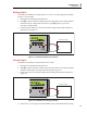
push L to turn on the Product internal 24 V supply in series with the current
measuring circuit. The top line changes to 24mA LPWR to show that the supply is
on. Push L again to turn off the supply and the top line reverts to 50mA RANGE.
5. If a 250 Ω resistor is necessary during a HART calibration procedure, push to
switch in the Product internal 250 Ω resistor. HART is added to the top line of the
display to show that the resistor is turned on in the circuit. Push again to turn off
the resistor and the display changes to its previous condition. This resistor lowers the
maximum-load driving function from 1000 Ω at 20 mA to 750 Ω at 20 mA.
Pressure Input
The isolated pressure display uses the same physical pressure connector as the primary
display. It is possible to have the displays set to show pressure at the same time. The
same source can be shown in different pressure units. See the “Pressure Measure” in
Chapter 2 for a discussion on pressure module selection.
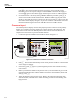
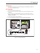
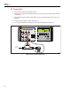
1. Connect the pressure module to the Product as shown in Figure 3-3.
CURRENT
OUTPUT
HI
VOLTS
mA
RTD/
OUTPUT
HI
LO
HI
LO
LO
TC
SENSE
INPUT/OUTPUT
4
W RTD/
INPUT
100 V PK
MAX
100V MAX
100mA MAX
20V PK
MAX
20V PK
MAX
PRECISION PROCESS CALIBRATOR
7526A
100 V PK
MAX
HI
INPUT
LO
Switch Test
Reset
LOOP
HART
PWR
Press and Hold
or Switch Test
VOLTS
mA
Pressure
Module
gwp019.eps
Figure 3-3. Isolated Pressure Module Connection
2. Push . The Product automatically senses which pressure module is connected and
sets its range accordingly.
3. If necessary, push again to cycle through the pressure units until the necessary
unit is shown.
4. Before you attach the module to the pressure source, zero the module as given in the
instruction sheet that came with the module. Procedures can be different, but all end
with and .
5. Attach the module to the pressure source. Refer to the instruction sheet that came
with the module, and make sure to follow all safety precautions when dealing with
high pressures.