
Product Manual


7526A
Users Manual
3-6
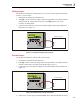
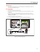
After the second contact transition, the switch opens. After the second contact
transition, the Calibrator enters the recall mode:
gwp035.eps
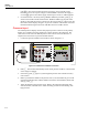
2. Push .
gwp038.eps
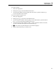
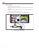
3. Push .
gwp039.eps
When necessary, push L to reset the switch test. Hold down for 3 seconds
to put the Calibrator into the isolated input mode that was selected before.
Output Setpoints
Nine preset output setpoints can be stored and recalled for each of these output modes:
• Voltage
• Current
• Each thermocouple type, this includes millivolts
• Each RTD type, this includes each of the five custom curves
They can be recalled on an individual basis or as an automatic up and down cycle with a
configurable dwell time between each setpoint. The automatic cycle feature starts at
setpoint number 1 and steps to a user-specified end setpoint number. It then goes back
down in reverse sequence and cycles through the sequence again.
To set a setpoint:
1. Select the output mode.
2. Type the output value for the setpoint.
3. Push and to select the SET function.
4. At the setpoint number selection prompt "SET POINT#", push the numeric key, 1 to
9, for the setpoint to be set.
5. If the automatic cycle feature is to be used, make sure to correctly sequence the
setpoint values. It always cycles between setpoint number 1 and a user-specified end
setpoint number. The values in the cycled group of setpoints must be keyed in with
this in mind. Random setpoints used for individual checks can then be found after the
usual end setpoint number.