
Product Manual


Application Notes
Introduction 4
4-3
Introduction
This chapter includes application notes that will help you to understand how to better use
the Product under different situations.
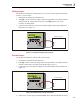
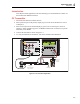
P/I Transmitter
1. Disconnect test leads from external devices.
2. Select pressure input on the primary display as given in the “Pressure Measure” section
of Chapter 4.
3. Select current input on the isolated display as given in the “Current Input” section of
Chapter 5. Select isolated loop power. If a HART communicator is used for set up of the
transmitter, select HART.
4. Connect the transmitter as shown in Figure 4-1.
5. To verify and calibrate the transmitter, refer to the transmitter documentation.
CURRENT
OUTPUT
HI
VOLTS
mA
RTD/
OUTPUT
HI
LO
HI
LO
LO
TC
SENSE
INPUT/OUTPUT
4
W RTD/
INPUT
100 V PK
MAX
100V MAX
100mA MAX
20V PK
MAX
20V PK
MAX
PRECISION PROCESS CALIBRATOR
7526A
100 V PK
MAX
HI
INPUT
LO
Switch Test
Reset
LOOP
HART
PWR
Hand Pump
or
Precision Regulated
Supply Pressure
Vent to
Atmosphere
Press and Hold
for Switch Test
VOLTS
mA
Pressure Module
Documenting
Process
Calibrator
754
DOCUMENTING PROCESS CALIBRATOR
gwp020.eps
Figure 4-1. P/I Transmitter Application