
User's Manual


43B
Service Information
7-6
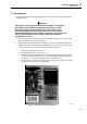
1. Check the SLOW ADC, see 7.5.3.
2. Check VGARVAL (N501 pin 64), for +3.3V. If not correct, check if the line
is shorted to ground. If it is not, then replace N501.
3. Trace the CHARCURR signal path to R534, R 442 and D471A (D-ASIC)
output pin B8.
d. Check the following:
1. C506 and connections to N501.
2. Connections between V506 and N501 pin 16 (CHAGATE).
3. The voltage at TP501 (N501 pin 19, VCHDRIVE) for ≅ 15...20V.
4. The voltage at N501 pin 43 for a triangle waveform, 80...100 kHz, +1.6V to
+3.2V.
5. If 1 to 4 correct, then replace N501.
7.4 Starting with a Dead Test Tool
If the test tool cannot be turned on, when powered by a charged battery pack, or by the
power adapter, follow the steps below to locate the fault.
1. Connect a power adapter and a charged battery pack.
2. Turn the test tool on and listen if you hear a beep.
a. If you hear no beep, continue at 7.4.1 Test Tool Completely Dead.
b. If you hear a weak beep, continue at 7.4.2 Test Tool Software Does not Run.
c. If you hear a “normal” beep, the software runs, but obviously the test tool is not
operative. Continue at 7.4.3 Software Runs, Test Tool not Operative.
7.4.1 Test Tool Completely Dead
1. Turn the test tool off. Keep the arrow keys pressed, and turn the test tool on
again. This will start up the mask software.
If you still hear no beep, continue at step 2.
If you hear a weak beep now, continue at 7.4.2.
2. Check the Keyboard ROW1 line (MS433 next to X452) for a 100 kHz square wave.
If not correct, continue at step 3.
If correct, the mask software runs, but the buzzer circuit does not function. Check
the buzzer function ( 7.5.10), and then continue at 7.4.2.
3. Check N501 pin 60 (VBATSUP) for >4.8V. If not correct check R503, and
connections to battery pack.
4. Check + of C568 or TP571 (+3V3GAR) for +3.3V.
If not correct, this is possibly caused by V569, R580, + of C568 short to ground,
loose pins of N501, or N501 defective. Check the +VD supply voltage on D-ASIC
D471A. Temporarily remove R470 to check for short circuit.
5. Check N501 pin 64 (VGARVAL) for +3.3V. If not correct:
a. Check if the line is shorted to ground.
b. Check N501 pin 73 (REFPWM2) for +3V3. REFPWM2 is supplied by N501,
and derived from REFP on the reference circuit on the Trigger part. Check