
User's Manual

Performance Verification
4.5 Input 1 and Input 2 Tests in the SCOPE MODE. 4
4-15
• Press to confirm; mark changes to .
• Press
to return to SCOPE.
11. Set the 5500A to source +3V DC.
12. Set the trigger level to +2 divisions from the screen center. For negative slope
triggering, the trigger level is the bottom of the trigger icon (
).
• Press
to select TRIGGER.
• Using
set the trigger level to +2 divisions from the screen center.
13. Verify that no trace is shown on the test tool display, and that at the upper right
corner of the display HOLD is not shown. If the display shows HOLD then press
. Hold should disappear and the test tool is re-armed for a trigger.
14. Decrease the 5500A voltage slowly in 0.1V steps, using the 5500A EDIT FIELD
function, until the test tool is triggered, and the traces are shown.
15. Verify that the 5500A voltage is between +1.5V and +2.5V when the test tool is
triggered.
To repeat the test, start at step 12.
16. When you are finished, set the 5500A to Standby.
4.5.8 Input 1 and 2 DC Voltage Accuracy Test.
WARNING
Dangerous voltages will be present on the calibration source
and connecting cables during the following steps. Ensure that
the calibrator is in standby mode before making any connection
between the calibrator and the test tool.
Proceed as follows:
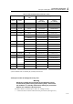
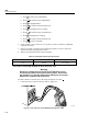
1. Connect the test tool to the 5500A in Figure 4-5.
ST8001.CGM
Figure 4-5. Test Tool Input 1-2 to 5500A Normal Output
2. Select the AUTO test tool setup:
• Press
to select the MENU.
• Press
till SCOPE is highlighted.