
User's Manual

Performance Verification
4.5 Input 1 and Input 2 Tests in the SCOPE MODE. 4
4-19
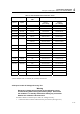
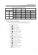
Table 4-3. Volts AC Measurement Verification Points
Sensitivity Time
base
5500A output
Volts rms
5500A
Frequency
Reading 1 & 2
Input 1 Input 2 Input 1 Input 2
200 mV/div 200A/div 10 ms/d 500 mV 60 Hz 494.0 to 506.0 494.0 to 506.0
20 μ/d 500 mV 20 kHz 486.0 to 514.0
2V/div 2kA/div 20 μ/d 5V 20 kHz 4.860 to 5.140
10 ms/d 5V 60 Hz 4.940 to 5.060 4.940 to 5.060
20V/div 20kA/div 10 ms/d 50V 60 Hz 49.40 to 50.60 49.40 to 50.60
20 μ/d 50V 20 kHz 48.60 to 51.40
1)
The 500V and 1250V range will be tested in Section 4.5.14
4.5.10 Input 1 and 2 AC Input Coupling Test
Proceed as follows to test the Input 1 and 2 AC coupled input lower transition point:
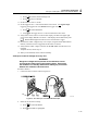
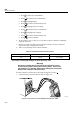
1. Connect the test tool to the 5500A as for the previous test (see Figure 4-5).
2. Select the AUTO test tool setup:
• Press
to select the MENU.
• Press
till SCOPE is highlighted.
• Press
to select SCOPE mode
3. Select AC coupling & reading for Input 1 and 2.
• Press
to select menu SCOPE SETUP.
• Press
to select Input 1 READING.
• Press
to highlight ACrms.
• Press
to confirm; mark changes to .
• Press
to highlight Input 1 Coupling.
• Press
to select the Input 1 Coupling menu.
• Press
to highlight AC Coupling.
• Press
to confirm; mark changes to .
• Press
select Input 2 READING.
• Press
to select the Input 2 READING
• Press
to highlight ACrms.
• Press
to confirm; mark changes to .
• Press
to highlight Input 2 Coupling.