
User's Manual


43B
Service Information
4-26
3. Set the 5500A to the first test point in Table 4-8.
Use the 5500A “COMP 2 wire” mode for the verifications up to and including 50 kΩ.
For the higher values, the 5500A will turn off the “COMP 2 wire” mode.
4. Observe the Input 1 main reading and check to see if it is within the range shown
under the appropriate column.
5. Continue through the test points.
6. When you are finished, set the 5500A to Standby.
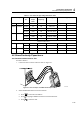
Table 4-8. Resistance Measurement Verification Points
5500A output Reading
0Ω 000.0 to 000.5
400Ω 397.1 to 402.9
4 kΩ 3.971 to 4.029
40 kΩ 39.71 to 40.29
400 kΩ 397.1 to 402.9
4 MΩ 3.971 to 4.029
30 MΩ 29.77 to 30.23
4.6.2 Diode Test Function Test
Proceed as follows to test the Diode Test function :
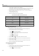
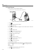
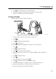
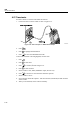
1. Connect the test tool to the 5500A as for the previous test (see Figure 4-7).
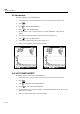
2. Select OHMS/CONTINUITY/CAPACITANCE:
• Press
to select the main MENU.
• Press
to highlight OHMS/CONTINUITY/CAPACITANCE.
• Press
to select the item.
• Press
to select DIODE.
3. Set the 5500A to 1 kΩ. Use the 5500A “COMP 2 wire” mode.
4. Observe the main reading and check to see if it is within 0.425 and 0.575V.
5. Set the 5500A to 1V DC.
6. Observe the main reading and check to see if it is within 0.975 and 1.025V.
7. When you are finished, set the 5500A to Standby.
4.6.3 Continuity Function Test
Proceed as follows:
1. Connect the test tool to the 5500A as for the previous test (see Figure 4-7).
2. Select OHMS/CONTINUITY/CAPACITANCE:
• Press
to select the main MENU.