732/1734 Energy Logger Users Manual February 2017 Rev. 1, 7/17 ©2017 Fluke Corporation. All rights reserved. All product names are trademarks of their respective companies. Specifications are subject to change without notice.
LIMITED WARRANTY AND LIMITATION OF LIABILITY Each Fluke product is warranted to be free from defects in material and workmanship under normal use and service. The warranty period is two years and begins on the date of shipment. Parts, product repairs, and services are warranted for 90 days.
Table of Contents Title Page Introduction. . . . . . . . . . . . . . . . . . . . . . . . . . . . . . . . . . . . . . . . . . . . . . . . . . . . . . . . . . . . . . . . . . . . . . . . . . . . . .1 How to Contact Fluke . . . . . . . . . . . . . . . . . . . . . . . . . . . . . . . . . . . . . . . . . . . . . . . . . . . . . . . . . . . . . . . . . . . . . .1 Safety Information . . . . . . . . . . . . . . . . . . . . . . . . . . . . . . . . . . . . . . . . . . . . . . . . . . . . . . . . . . . . . . . . .
1732/1734 Users Manual Touch Screen . . . . . . . . . . . . . . . . . . . . . . . . . . . . . . . . . . . . . . . . . . . . . . . . . . . . . . . . . . . . . . . . . . . . . . . . . . .18 Brightness Button . . . . . . . . . . . . . . . . . . . . . . . . . . . . . . . . . . . . . . . . . . . . . . . . . . . . . . . . . . . . . . . . . . . . . 18 Calibration . . . . . . . . . . . . . . . . . . . . . . . . . . . . . . . . . . . . . . . . . . . . . . . . . . . . . . . . . . . . . . . . . . . . . . . . . . .
Contents (cont.) Energy Analyze Plus Software . . . . . . . . . . . . . . . . . . . . . . . . . . . . . . . . . . . . . . . . . . . . . . . . . . . . . . . . . . . . . . 49 System Requirements . . . . . . . . . . . . . . . . . . . . . . . . . . . . . . . . . . . . . . . . . . . . . . . . . . . . . . . . . . . . . . . . . . 49 PC Connections . . . . . . . . . . . . . . . . . . . . . . . . . . . . . . . . . . . . . . . . . . . . . . . . . . . . . . . . . . . . . . . . . . . . . . 50 WiFi Support. . . . . . .
1732/1734 Users Manual iv
Introduction How to Contact Fluke The 1732 and 1734 Energy Loggers (the Logger or Product) are compact devices for energy and power quality surveys. With a built-in touch screen and USB flash drive support, it is easy to configure, verify, and download measurement sessions without the need of a computer at the measurement location. All illustrations in this manual show the 1734.
1732/1734 Users Manual Safety Information A Warning identifies hazardous conditions and procedures that are dangerous to the user. A Caution identifies conditions and procedures that can cause damage to the Product or the equipment under test. damaged or if the insulation shows signs of wear. • Use Product-approved measurement category (CAT), voltage, and amperage rated accessories (probes, test leads, and adapters) for all measurements.
Energy Logger Safety Information • Do not exceed the Measurement Category (CAT) rating of the lowest rated individual component of a Product, probe, or accessory. • Do not use USB accessories when the Product is installed in environment with wires or exposed metal parts with hazardous live voltage such as in cabinets. • Keep fingers behind the finger guards on the probes.
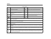
1732/1734 Users Manual Table 1. Symbols Symbol 4 Description Symbol Description Consult user documentation. WARNING. RISK OF DANGER. Conforms to relevant Australian EMC standards. WARNING. HAZARDOUS VOLTAGE. Risk of electric shock. Certified by CSA Group to North American safety standards. Earth Conforms to European Union directives.
Energy Logger Before You Start Before You Start The 1734 Energy Logger also includes these items in the standard purchase list: Below is a list of the items included with your purchase. Carefully unpack and inspect each of the items: • WiFi/BLE to USB Adapter • Magnet Hanger Kit • Set of 4 Magnet Probes for 4 mm Banana Plugs • • • • • • • • • • • • • • Energy Logger Power Supply Voltage Test Lead, 3-phase + N 4x Dolphin Clips, Black 3x i173x-flex1500 Thin-Flexi Current Probe, 30.
1732/1734 Users Manual WiFi and WiFi/BLE-to-USB Adapter The USB adapter enables the wireless connectivity of the Logger: 1 2 3 4 • Connection to the Fluke Connect smartphone app for easy asset management and data sharing. • Data transfer to "Energy Analyze Plus" PC software. • Remote control via Virtual Network Computing (VNC). See Remote Control on page 52 for more information about VNC.
Energy Logger Before You Start Magnet Hanger Kit The accessory shown in Figure 2 is used to: • Hang the Logger with power supply attached (use two magnets) • Hang the Logger separately (use two magnets) • Hang the power supply separately (use one magnet) Voltage Test Leads Voltage test leads are four-core, flat, test leads that do not tangle and can be installed in tight spaces.
1732/1734 Users Manual Thin-Flexi Current Probe The R-coil has advantages over other types of current transformers: The Thin-Flexi Current Probe works on the Rogowski coil (R-coil) principle that is a toroid of wire used to measure an alternating current through a wire encircled by the toroid. See Figure 3. • It is not a closed loop. The second terminal is passed back through the center of the toroid core (commonly a plastic or rubber tube) and connected along the first terminal.
Energy Logger Before You Start Use the color clips for easy identification of the four current probes. Apply the clips that are appropriate for your local wiring codes on both ends of the current probe cable. See Figure 4. Kensington Lock A Kensington Security Slot (also called a K-Slot or Kensington lock) is part of a built-in anti-theft system. It is a small, metal-reinforced, oval hole found on the right side of the Logger (see item 6 in Table 4). It is used for attaching a lock-and-cable apparatus.
1732/1734 Users Manual Accessories Table 3 is a list of the accessories that are available and sold separately for the Logger. The warranty on included accessories is 1 year. For the most up-to-date information on accessories, go to www.fluke.com. Table 3. Accessories Part ID Description i17xx-flex 1500 Thin-Flexi Current Probe (single) 1500 A, 30.5 cm (12 in.
Energy Logger Storage Storage When not in use, keep the Logger in the protective storage bag/case. The bag/case has sufficient space for the Logger and all the accessories. If the Logger is stored for an extended period of time or is not in use for a long time, you should charge the battery at least once every six months. The power cord/measurement line cover slides to select the input source.
1732/1734 Users Manual Battery Operation Caution To prevent damage to the Product: • Do not leave batteries unused for extended periods of time, either in the product or in storage. • When a battery has not been used for six months, 1. Connect the mains cord to the ac input socket on the power supply. 2. Fit the power supply to the Logger or use the dc power cord to connect the power supply to the Logger. 3. Connect to mains power. check the charge status and charge the battery as appropriate.
Energy Logger Navigation and User Interface Navigation and User Interface See Table 4 for a list of the front panel controls and their functions. See Table 5 for a list of the connectors and their functions. Table 4.
1732/1734 Users Manual Table 5.
Energy Logger Connector Panel Decal Connector Panel Decal A self-adhesive decal is supplied with the Logger. The decal corresponds to the wiring color codes used in your local area of operation. Apply the decal around the current and voltage inputs on the connector panel as shown in Table 6. Table 6.
1732/1734 Users Manual Power The Logger has options for power source: • mains • measurement line • battery Measurement Line Power Source 1. Attach the Power Supply to the Logger or use the dc power cord to connect the Power Supply to the Logger. 2. Move the slide-cover on the power supply to access the safety sockets and connect these sockets with the voltage input sockets A/L1 and N. The front panel LED shows the status. See Table 7 for more information.
Energy Logger Power Battery Power Source Table 7. Power/Battery Status The Logger can operate on battery power without a connection to the power supply or dc power cord. Logger On Push . The Logger turns on and is ready to use in <30 seconds. The battery symbol in the status bar and the power LED indicate the battery status. See Table 7.
1732/1734 Users Manual Touch Screen The touch screen lets you interact directly with what is on the display. To change parameters, touch a target on the display. Touch targets are easy to recognize, such as large buttons, items in menus, or keys of the virtual keyboard. The Product can be operated with insulating gloves on (resistive touch). Brightness Button The touch screen has a backlight for work in dimly lit spaces. See Table 4 for the location of the Brightness () button.
Energy Logger First-time Use/Setup Wizard First-time Use/Setup Wizard To start the Logger: 1. Install WiFi/BLE or WiFi only adapter (see WiFi and WiFi/BLE-toUSB Adapter on page 6). 2. Attach the power supply to the Logger or use the dc power cable to connect the power supply with the Logger. 3. Connect the power cord into the power supply. The Logger starts up in <30 seconds and the Setup Wizard starts. 4. Pick the language (see Instrument Settings on page 39). 5.
1732/1734 Users Manual First Measurements 7. Connect the voltage test leads to neutral, phase A/L1, phase B/L2, and phase C/L3. At the energy study site, look at the information in the panel and the rating plates on the machines. Based on knowledge of the electrical supply in the facility, determine the configuration. 8. With all of the connections done, check that the voltages for phases A/L1, B/L2, and C/L3 are as expected. 9. Read the current measurements for phases A/L1, B/L2, and C/L3.
Energy Logger Function Selection Buttons 17. Review the logged data using the softkeys V, A, Hz, +, Power, and Energy. Function Selection Buttons 18. To prevent unwanted operation, touch the Lock Screen target. The default PIN to lock/unlock the screen is 1234. See Screen Lock on page 42 f or more information. The Logger has three buttons that switch between the Meter, Power, and Logger function modes. The current mode shows in the upper left corner of the display. 19.
1732/1734 Users Manual THD Voltage includes a traffic light indicator: Study Type • green: <2 % • yellow: 2 % to 8 % • red: >8 % Depending on the application, select either Load Study or Energy Study. Note A Voltage THD of >8 % exceeds the limits of Power Quality standards. A detailed analysis of the harmonics with a power quality analyzer is recommended when the THD shows a yellow or red indicator.
Energy Logger Function Selection Buttons Single Phase Single Phase IT Example: Branch circuit at an outlet. The logger has a galvanic isolation between the voltage inputs and ground based signals like USB and mains input. A/L1 Example: Used in Norway and in some hospitals. This would be the connection at a branch circuit.
1732/1734 Users Manual Split Phase 3-Ф Wye Example: A North American residential installation at the service entrance. Example: Also called “Star” or four-wire connection. Typical commercial building power.
Energy Logger Function Selection Buttons 3-Ф Wye IT 3-Ф Wye Balanced The logger has a galvanic isolation between the voltage inputs and ground based signals like USB and mains input. Example: For symmetrical loads like motors the connection can be simplified by measuring only one phase and assuming the same voltages/currents on the other phases. Example: Industrial power in countries that use the IT (Isolated Terra) system, such as Norway.
1732/1734 Users Manual 3-Ф Delta 2 Element Delta (Aron/Blondel) Example: Often found in industrial settings where electric motors are used. Example: Blondel or Aron connection, simplifies the connection by the use of only two current sensors.
Energy Logger Function Selection Buttons 3-Ф Delta Open Leg 3-Ф High Leg Delta Example: A variant of power transformer winding type. Example: This topology is used to provide an additional voltage that is half the phase to phase voltage. A/L1 A/L1 B/L2 C/L3 B/L2 C/L3 N Energy Study Energy Study A/L1 A/L1 B/L2 C/L3 B/L2 C/L3 N Load Study (no voltage measurement) Load Study (no voltage measurement) Note The Logger provides the data of the 3-φ Delta system.
1732/1734 Users Manual 3-Ф Delta Balanced Nominal Voltage Example: For symmetrical loads like motors, the connection is simplified with only one phase measurement and assuming the same voltages/currents on the other phases. In load studies only, select a nominal voltage from the list. If a voltage is not shown in the list, enter a custom voltage.
Energy Logger Function Selection Buttons Note Set the current range to Auto when you are not sure about the maximum current during the logging session. A specific application can require you to set the current range to a fixed range rather than Auto. This can occur because the Auto range is not gapless and may lose too much information in the case of a highly fluctuating current. 3. On the Logger, select AUX 1 or AUX 2. Active FC sensors within a 10 m range show in the selection list on the Logger.
1732/1734 Users Manual 1 2 3 Select 4 1 Confirm Flashes 5 6 Figure 6.
Energy Logger Function Selection Buttons Wired Connection Configure the Auxiliary input to show the readings for the attached sensor. In addition to the default setting of ±10 V, up to five custom sensors can be configured and selected for the Auxiliary input channels. To configure custom sensors: 1. Select one of the five custom sensors. 2. When the sensor has not been configured, push (Edit) to access the configuration screen. 3.
1732/1734 Users Manual Example 2: 1. Push (Show Menu) and select Verify. Output: 1 mV/°C, 1 mV/°F 2. Push to toggle between Generator Mode and Motor Mode.
Energy Logger Function Selection Buttons Correct Digitally Push (Show Menu) and select Correct Digitally to access the Power connection correction screen. This screen allows you to virtually swap phases and invert the current inputs instead of a manual correction. chart for each phase (A, B, C or L1, L2, L3) and total as: In three phase systems, the algorithm creates a sequence with a clockwise phase rotation.
1732/1734 Users Manual The menu also provides the access to live values of Energy as: Logger • Active Energy (Ep) Wh – In Logger mode, you can: • Reactive Energy (EQr) in varh • Configure a new logging session • Apparent Energy (Es) in V Ah • Review the data of an ongoing logging session in memory To display a trend chart of the last 7 minutes of Power values: • Review the data of a completed logging session (as long as no 1. Push (Live-Trend). 2.
Energy Logger Function Selection Buttons To select between Load Study and Energy Study: Duration and Recording Start/Stop Date and Time 1. Go to Meter > Change Configuration. This Configuration screen contains the measurement configuration parameters such as Topology, current range, voltage, and current ratios. You can set the duration of the measurement from a list. No end configures the maximum possible duration based on the available memory. 2.
1732/1734 Users Manual Options to configure the logging session: • Duration and manual start • Duration and set start date/time • Set start date/time and set end date/time A memory gauge shows the memory used by recorded sessions and stored screenshots in black. The memory required for the new session is shown in green. When the new logging session will not fit in the available memory, the gauge turns from green to red.
Energy Logger Function Selection Buttons Energy costs From the Logger home screen you have access to: Enter the costs/kWh for demand energy. The energy costs are applied to forward energy (positive energy) using the demand interval and can be reviewed in the Logger detail screen Energy - Demand. • • • • Energy costs can be entered using a resolution of 0.001. The currency unit is changed in Instrument Settings. See Instrument Settings on page 39 for more information.
1732/1734 Users Manual The algorithm to calculate Voltage min/max values is in accordance to established power quality standards to detect dips, swells, and interruptions. Watch for values exceeding ±15 % of the nominal voltage. This is an indicator of power quality problems. High maximum values on Currents can be an indicator for tripping circuit breakers. Push (Graph) to display the measured values in a chart.
Energy Logger Function Selection Buttons Memory/Settings Button Screen Capture In this menu you can: In this screen you can review, erase, and copy saved screens to a USB flash drive. • Review and erase the data from completed logging sessions • Review and erase screen captures • Copy measurement data and screen captures to the USB flash 1. Push . 2. Push (Screen Capture) to show the list of all screens. See Basic Navigation on page 18 for more information about how to capture screens. 3.
1732/1734 Users Manual Name for Instrument Phase Color/Phase Labels You can assign a name to the Logger. This name is attached to the measurement files when you review these files in Energy Analyze Plus software. The default name is FLUKE173x, for example: FLUKE1734<12345678>. The phase colors are configurable to match with the connector panel decal: Scheme A/L1 B/L2 C/L3 N To change the instrument name: US black red blue white 1. Push . Canada red black blue white 2.
Energy Logger Function Selection Buttons Date/Time Zone To set the date format: The logger stores the measurement data in universal time coordinate (UTC) to ensure continuity in time and accounts for time changes due to daylight saving time (DST). 1. Push . 2. Push (Instrument Settings). 3. Push / to highlight the Date Format target and push or touch the Date Format target. 4. Select one of the available date formats. 5. Push to toggle between a 12 hour or 24 hour format.
1732/1734 Users Manual Currency Status Information The currency symbol used for energy cost values is configurable. The screen provides information and status about the Logger, such as the serial number, attached current probes, battery status, and installed licenses. To set the currency: 1. Push . 2. Push (Instrument Settings). 3. Push / to highlight the Currency target and push or touch the Currency target. To go to the status information: 1. Push . 2. Push (Instrument Settings).
Energy Logger Function Selection Buttons Touch Screen Calibration Copy Service Data to USB The touch screen has been calibrated at the factory before shipment. In case you do experience misalignment with the touch targets, use the touch screen calibration feature. If requested for customer support, use this function to copy all measurement files in raw format and system information to a USB flash drive. To calibrate: To copy the service data: 1. Push . 2. Push (Instrument Settings).
1732/1734 Users Manual Reset to Factory Defaults 2. Copy the firmware file (*.bin) into this folder. The reset function deletes all user data, such as logging sessions and screen captures. It also deletes the WiFi access point connection credentials, and sets the instrument settings to default values. It also enables the first-time use wizard the next time the instrument restarts. 3. Make sure the Logger is powered from mains and turned on. 4. Plug the flash drive into the Logger.
Energy Logger Licensed Features Licensed Features 7. The WiFi Infrastructure license is complimentary and enabled when you register the Logger. Note The activation of the WiFi Infrastructure does not require a license key. This license activates the connection to a WiFi infrastructure. See WiFi-Infrastructure on page 51 for details. To activate a license from a PC: 1. Go to www.fluke.com. 2. Go to the product registration page and select your region, country, and language. 3.
1732/1734 Users Manual Maintenance If the Logger is used appropriately it does not require special maintenance. Maintenance should only be done at a company related service center by trained and qualified personnel within the guarantee period. See www.fluke.com for locations and contact information of Fluke Service Centers worldwide. Warning To prevent possible electrical shock, fire, or personal injury: • Do not operate the Product with covers removed or the case open.
Energy Logger Service and Parts Calibration Service and Parts As an additional service Fluke offers the regular examination and calibration of your Logger. The recommended calibration cycle is 2 years. For more information see How to Contact Fluke on page 1. Replacement parts are listed in Table 8 and shown in Figure 7. To order parts and accessories, see How to Contact Fluke on page 1. Table 8. Replacement Parts Ref. Description Fluke Part or Model Number Qty.
1732/1734 Users Manual 1 4 5 2 9 3 7 6 10 8 Figure 7.
Energy Logger Energy Analyze Plus Software Energy Analyze Plus Software Purchase of the Logger includes Fluke Energy Analyze Plus software. With the software, you can do many tasks from a computer: • Download campaign results for further processing and archiving. • Analyze energy or load profiles, including zoom-in and zoom-out on details. • Add comments, annotations, pictures, and other supplementary information to campaign data. • Overlay data from different campaigns to identify and document changes.
1732/1734 Users Manual WiFi Support PC Connections To connect the PC to the Logger: 1. Turn on the computer and the Logger. 2. Install the Energy Analyze Plus Software. 3. Connect the USB cable to the USB ports of the computer and the Logger. See Figure 8.
Energy Logger WiFi Support WiFi Direct Connection WiFi-Infrastructure The WiFi direct connection uses WPA2-PSK (pre-shared key) with AES encryption. The passphrase shown on the screen is required to establish a connection from a client to the device. 1. On the client, go to the list of available WiFi networks and look for a network with the name: “Fluke173x” for example: “Fluke1732<12345678>”. 2. Enter the passphrase provided on the WiFi Configuration screen when you are asked.
1732/1734 Users Manual Remote Control Configuration You can remotely control the instrument with a free third-party VNC client available for Windows, Android, Apple iOS, and Windows Phone after the WiFi connection is setup. VNC (Virtual Network Computing) allows you to see the screen content, push the buttons, and touch the targets. Tested VNC clients that work with the Logger are listed in Table 9. Table 9. VNC Clients Operating System Program Available from: Windows 7/8.x/10 TightVNC www.tightvnc.
Energy Logger Wireless Access to PC Software Wireless Access to PC Software Once the WiFi connection to the device is setup, no further setup is required to use WiFi communication with the Fluke Energy Analyze Plus software. The WiFi connection supports downloading the measurement files and screenshots and synchronizing the time. The selected communication media is shown in brackets. Refer to the online help for details about how to use the PC software.
1732/1734 Users Manual Wiring Configurations 2 Element Delta Aron/ Blondel 3-Ф Delta Open Leg (3P-3W) 3-Ф High Leg Delta Balanced 3-Ф Delta [2] 3-Ф Wye Balanced 3-Ф Wye 3-Ф Wye IT (3P-4W) Split Phase (2P-3W) Single Phase Single Phase IT [2] V [1] V [1] V [1] VAB V VBC[1] V VCA[1] V IA A IB A IC A f Hz Aux 1, 2 V, user defined THD VA [3] % THD VB [3] % THD VC[3] % VCN [2] VAN[1] VB
Energy Logger Wiring Configurations var QB, QB fund[3] var QC, QC fund[3] var QTotal, QTotal fund[3] var SA[1] VA SB[1] VA [1] VA SC STOTAL[1] VA PFA[3] PFB[3] PFC[3] [3] PFTotal ● Simulated in load studies if Unom is specified [2] Secondary displayed values [3] Measured values [1] ○ Balanced 3-Ф De
1732/1734 Users Manual General Specifications Color LCD Display.................................................4.3-inch active matrix color TFT, 480 pixels x 272 pixels, resistive touch panel Power/Charging/LED Indicator Warranty Logger and Power Supply ...................................2 years (battery not included) Accessories .........................................................1 year Calibration Cycle ...................................................2 years Dimensions Logger ...................
Energy Logger Environmental Specifications Safety IEC 61010-1 IEC Mains Input...............................................Overvoltage Category II, Pollution Degree 2 Voltage Terminals ...........................................Overvoltage Category IV, Pollution Degree 2 IEC 61010-2-033.................................................CAT IV 600 V / CAT III 1000 V Electromagnetic Compatibility (EMC) International ........................................................
1732/1734 Users Manual Electrical Specifications Power Supply Voltage Range ....................................................nominal 100 V to 500 V (85 V min to 550 V max) using safety plug input Mains Power .......................................................nominal 100 V to 240 V (85 V min to 265 V max) using IEC 60320 C7 input (figure 8 power cord) Power consumption.............................................Maximum 50 VA (max. 15 VA when powered using IEC 60320 input) Standby Power .............
Energy Logger Electrical Specifications Auxiliary Inputs Wired Connection Number of Inputs.............................................2 Input Range.....................................................0 V dc to ± 10 V dc Wireless Connection (requires WiFi/BLE adapter USB1 FC) Number of Inputs.............................................2 Supported Modules .........................................Fluke Connect 3000 series Acquisition...........................................................
1732/1734 Users Manual Demand Interval (Energy Meter Mode) Measured Parameter ..........................................Energy (Wh, varh, VAh), PF, Maximum Demand, Cost of Energy Averaging Interval ...............................................User selectable: 5 min, 10 min, 15 min, 20 min, 30 min, off Standards Compliance Harmonics ...........................................................IEC 61000-4-7: Class 1 Power ..................................................................
Energy Logger Electrical Specifications Accuracy at Reference Conditions Parameter Maximum Resolution Range Intrinsic Accuracy at Reference Conditions (% of Reading + % of Range) 1000 V 0.1 V ±(0.2 % + 0.01 %) 15 mV 0.01 mV ±(0.3 % + 0.02 %) 150 mV 0.1 mV ±(0.3 % + 0.02 %) 50 mV 0.01 mV ±(0.2 % + 0.02 %) 500 mV 0.1 mV ±(0.2 % + 0.02 %) 150 A 0.01 A ±(1 % + 0.02 %) 1500 A 0.1 A ±(1 % + 0.02 %) 300 A 1A ±(1 % + 0.03 %) 3000 A 10 A ±(1 % + 0.03 %) 600 A 1A ±(1.5 % + 0.
1732/1734 Users Manual Power/Energy Direct Input [1] Parameter iFlex1500-12 iFlex3000-24 iFlex6000-36 i40S-EL Clamp: 50 mV/500 mV Rogowski: 15 mV/150 mV 150 A / 1500 A 300 A / 3000 A 600 A / 6000 A 4 A / 40 A Clamp: 50 W/500 W Rogowski: 15 W/150 W 150 kW / 1.5 MW 300 kW / 3 MW 600 kW / 6 MW 4 kW / 40 kW 0.1 W 0.01 kW / 0.10 kW 1 kW / 10 kW 1 kW / 10 kW 1 W / 10 W Power Range W, VA, var Max. Resolution W, VA, var Max.
Energy Logger Electrical Specifications Intrinsic Uncertainty ±(% of measurement value + % of power range) Direct Input [1] Influence Quantity Parameter iFlex1500-12 iFlex3000-24 iFlex6000-36 i40S-EL Clamp: 50 mV/500 mV Rogowski: 15 mV/150 mV 150 A / 1500 A 300 A / 3000 A 600 A / 6000 A 4 A / 40 A PF ≥0.99 0.5 % + 0.005 % 1.2 % + 0.005 % 1.2 % + 0.0075 % 1.7 % + 0.0075 % 1.2 % + 0.005 % 0.1 ≤ PF <0.
1732/1734 Users Manual 2 1 – PF Formula 1: 0.5 + ------------------------- % +0.005 % 3 × PF 2 1 – PF Formula 2: 1.2 + ------------------------- % +0.005 % 2 × PF 2 1 – PF Formula 3: 1.2 + ------------------------- % +0.0075 % 2 × PF 2 1 – PF Formula 4: 1.7 + ------------------------- % +0.0075 % 2 × PF 2 1 – PF Formula 5: 1.2 + 1.7 × ------------------------- % +0.005 % PF Example: Measurement at 120 V/16 A using an iFlex1500-12 in low range.
Energy Logger Electrical Specifications iFlex Probe Specifications Measuring range iFlex 1500-12 ......................................................1 to 150 A ac / 10 to 1500 A ac iFlex 3000-24 ......................................................3 to 300 A ac / 30 to 3000 A ac iFlex 6000-36 ......................................................6 to 600 A ac / 60 to 6000 A ac Nondestructive current ........................................100 kA (50/60 Hz) Intrinsic Error at reference condition[1] .....
1732/1734 Users Manual 1/3 Phase shift...............................................................< ±0.5° C 1/3 B 1/3 A iFlex1500-12: 88mm iFlex3000-24: 185mm iFlex6000-36: 282mm Figure 9. iFlex Probe Window Bandwidth................................................................10 Hz to 23.5 kHz Frequency derating .................................................I x f ≤385 kA Hz Working Voltage ......................................................
Energy Logger Electrical Specifications Minimum bending radius .........................................38 mm (1.5 in) Output cable length iFlex 1500-12 ......................................................2 m (6.6 ft) iFlex 3000-24 & iFlex 6000-36 ............................3 m (9.8 ft) Weight iFlex 1500-12 ......................................................115 g iFlex 3000-24 ......................................................170 g iFlex 6000-36 ....................................................
1732/1734 Users Manual i40s-EL Current Clamp Specifications See Table 10 for setup instructions. Table 10. i40s-EL Setup Item AC 60 0 SE V R C IA L C U R R EN T AT N III U M BE C LA M Single Insulated current carrying conductor Release button Load direction arrow D Tactile barrier P R Measuring range .....................................................40 mA to 4 Aac / 0.4 Aac to 40 Aac Crest factor .............................................................
Energy Logger Electrical Specifications Influence of conductor position in jaw opening .........................................................±0.5 % of reading (@ 50/60 Hz) Bandwidth ...............................................................10 Hz to 2.5 kHz Working Voltage......................................................
1732/1734 Users Manual 70