438-II Motor Analyzer Users Manual March 2016 Rev. 1, 10/17 ©2016-2017 Fluke Corporation. All rights reserved. All product names are trademarks of their respective companies.
LIMITED WARRANTY AND LIMITATION OF LIABILITY Each Fluke product is warranted to be free from defects in material and workmanship under normal use and service. The warranty period is three years and begins on the date of shipment. Parts, product repairs, and services are warranted for 90 days.
Table of Contents Title Page Introduction. . . . . . . . . . . . . . . . . . . . . . . . . . . . . . . . . . . . . . . . . . . . . . . . . . . . . . . . . . . . . . . . . 1 How to Contact Fluke . . . . . . . . . . . . . . . . . . . . . . . . . . . . . . . . . . . . . . . . . . . . . . . . . . . . . . . . . 1 Safety Information . . . . . . . . . . . . . . . . . . . . . . . . . . . . . . . . . . . . . . . . . . . . . . . . . . . . . . . . . . . 2 In The Box . . . . . . . . . . . . . . . . . . . . . . . . .
38-II Users Manual ii
Introduction The Motor Analyzer is a feature that measures mechanical power, torque, and rpm on direct-on-line asynchronous motors or asynchronous motors driven by a variable speed drive (VSD). It is a standard feature on the Fluke 438-II and available as an optional upgrade for all models in the Fluke 430 Series II (Fluke 430-II/MA Motor Analyzer upgrade).
438-II Users Manual Safety Information A Warning identifies hazardous conditions and procedures that are dangerous to the user. A Caution identifies conditions and procedures that can cause damage to the Product or the equipment under test. XW Warning To prevent possible electrical shock, fire, or personal injury: • Read all safety information before you use the Product. • Use the Product only as specified, or the protection supplied by the Product can be compromised.
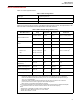
Motor Analyzer Motor Measurements Motor Measurements Table 1 is a list of supported motors: Table 1. Motor Configurations Motor type 3-phase asynchronous Motor measurement connection 3-Wire Direct on Line or 3-Wire connected to VSD Motor winding connection WYE or Delta Table 2 is a list of the range and accuracy of the Motor Analyzer-specific functions. See Specifications in the Fluke 430 Series II Users Manual for the specifications of the other functions. Table 2.
438-II Users Manual Motor Setup The motor nameplate provides information for the measurement algorithm. This information determines the mechanical parameters from the electrical signals that are used for measurements. It is critical that you enter the nameplate settings accurately to obtain accurate readings. To open the Motor Setup screen: 1. Push . The MENU screen opens. 2. Push to change the page view. 3. Use to move through the menu selections and highlight Motor Analyzer. 4.
Motor Analyzer Motor Setup Table 5. Motor Design Type and Characteristics Summary Motor Design NEMA-A NEMA-B NEMA-C NEMA-D NEMA-E IEC-H IEC-N Starting Current High Medium Medium Medium Medium Medium Medium Starting Torque Medium Medium High Very High Medium High Medium Breakdown Torque High Medium High Very High Medium High Medium Table 6.
438-II Users Manual See Table 7 for a list of the supported VSDs. Table 7. Supported Variable Speed Drives Drive Characteristics Supported Range Drive Output Frequency 41 Hz to 69 Hz Drive Type Voltage Source Inverter only Drive Control Method V/f (Volt over Hertz) only, open loop vector control, closed loop vector control, and drive with and without encoders Unit Setup Use the setup screen to set the analyzer limits and defaults. Softkeys: ANALYZER LIMITS Sets the Analyzer Limits.
Motor Analyzer Motor Setup Set Analyzer Limits You can adjust the default limit values that show the system performance in various bar graphs. The limits you enter here adjust where the bar graph shows the transition from orange to red. See Motor Analyzer Parameters on page 8 for more information. To change: 1. Use to change a default value. 2. Press to restore the default values. Trend Setup The Trend Setup screen is a simplified version of the normal TIMED START screen.
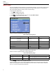
438-II Users Manual Motor Analyzer Parameters The MOTOR ANALYZER screen shows the important mechanical and electrical parameters relative to their rated values, industry standards, or the NEMA MG 1-2014 standard. A separate screen is available for the Mechanical Parameters and one for the Electrical Parameters. To open the screen: 1. Go to the MOTOR SETUP screen. 2. Press (START). 3. Use to move between the screens for electrical and mechanical parameters.
Motor Analyzer Motor Analyzer Parameters Electrical Parameters The second screen is the electrical power and power factor. It shows the voltage unbalance and harmonics voltage factor according to NEMA MG1. Use to move between the screens for electrical and mechanical parameters. Softkeys: View ANALYZER LIMITS screen. Select METER screen. Select DERATING screen. View MOTOR SETUP screen. STOP measurements and save measurement results.
438-II Users Manual Meter Screen The METER screen shows all measurements in the Motor Analyzer mode as a table view. Available readings: Motor Power (k)W or hp Torque Nm or lb.ft Note To select between kW or hp and Nm or lb.ft in, see Unit Setup on page 6.
Motor Analyzer Motor Analyzer Parameters Softkeys: to scroll through the METER screen. Opens the ANALYZER screen. Opens the TREND screen. Opens the MOTOR SETUP screen. STOP measurements and save measurement results. Trend The Trend screen is the standard trend function from the 43X-Series II that shows the recorded measurement data over time. Note The Power Quality EVENT capture function is not available in Motor Analyzer.
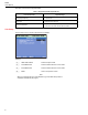
438-II Users Manual Derating Screen NEMA has guidelines for the application of induction motors to the characteristics of the power system. The NEMA standard MG 1 2014 recommends derating the permissible motor load if Voltage Unbalance or Voltage Harmonics exist in the power system. Note The Derating screen is not available when Variable Speed Drive is set to YES.
Motor Analyzer Motor Analyzer Parameters Voltage Harmonics Harmonic currents are introduced when the line voltages applied to the motor include voltage components at frequencies other than the fundamental frequency of the supply (50 Hz or 60 Hz). The temperature of the motor operating at a particular load and per unit voltage harmonic factor will therefore be greater than that for the motor operating under the same conditions with only voltage at the fundamental frequency applied.
438-II Users Manual The actual load and derating factor is indicated with a cross-hair. The green area indicates a motor that operates within rated limits. The yellow area indicates the permissible Service Factor area (the Service Factor is from the nameplate on the motor and entered in the Motor Setup screen). The red area indicates the overload area for the motor.