® 53 & 54 Series II Thermometer Users Manual September 1999 Rev.1, 6/01 © 1999-2001 Fluke Corporation, All rights reserved. Printed in USA All product names are trademarks of their respective companies.
Limited Warranty & Limitation Of Liability This Fluke product will be free from defects in material and workmanship for 3 years from the date of purchase. This warranty does not cover fuses, disposable batteries or damage from accident, neglect, misuse or abnormal conditions of operation or handling. Resellers are not authorized to extend any other warranty on Fluke’s behalf.
Table of Contents Title Safety Information.......................................................................................................... Contacting Fluke ....................................................................................................... Getting Started............................................................................................................... Components........................................................................................................
53 & 54 Series II Users Manual Displaying Temperatures........................................................................................... Holding the Displayed Temperatures ........................................................................ Viewing the MIN, MAX, and AVG Readings .............................................................. Using the Offset to Adjust for Probe Errors ............................................................... Using Memory ...................................
3 & 54 Series II Safety Information Contacting Fluke The Fluke Model 53 and Model 54 Thermometers (“the thermometer”) are microprocessor-based, digital thermometers designed to use external J-, K-, T-, E-, R-, S-, and N-type thermocouples (temperature probes) as temperature sensors. To order accessories, receive assistance, or locate the nearest Fluke distributor or Service Center, call: Use the thermometer only as specified in this manual.
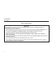
53 & 54 Series II Users Manual Table 1. Safety Information WWarning A Warning identifies conditions and actions that pose hazards to the user. To avoid electrical shock or personal injury, follow these guidelines: • Before using the thermometer inspect the case. Do not use the thermometer if it appears damaged. Look for cracks or missing plastic. Pay particular attention to the insulation around the connectors. • Disconnect the thermocouple(s) from the thermometer before opening the case.
53 & 54 Series II Safety Information Table 1. Safety Information (cont.) WWarning (cont.) • Model 54: Measurement errors may occur if voltages on the measurement surfaces result in potentials greater than 1 V between the two thermocouples. When potential differences are anticipated between the thermocouples, use electrically insulated thermocouples. • When servicing the thermometer, use only specified replacement parts. • Do not use the thermometer with any part of the case or cover removed.
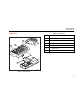
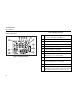
53 & 54 Series II Users Manual Table 2. International Symbols W Refer to the manual for information about this feature. P M Battery. Complies with European Union directives. Complies with relevant Canadian Standards Association directives. Getting Started • Figure 1 and Table 3 describe the components. Everything in this Users Manual applies both to Models 53 and 54 unless otherwise indicated. • Figure 2 and Table 4 describe the display. • Table 5 describes the functions of the buttons.
53 & 54 Series II Getting Started Table 3. Components Components xx 3 2 5 1 4 A Thermocouple T1 input B Model 54: Thermocouple T2 input C Holster D Display E Buttons F Battery door G Batteries 6 7 aat01f.eps Figure 1.
53 & 54 Series II Users Manual Display Elements Table 4. Display Elements xx 2 3 4 5 7 1 8 9 12 10 11 A The thermocouple measurement includes an offset. See "Changing Setup Options." B The displayed readings do not change. C A shift function is in progress. D Readings are being logged. E Setup is in progress. F Logged readings are displayed. G Low battery. Replace the batteries. H Primary Display. Model 53: T1 reading. Model 54: T1, T2, or T1-T2 reading. I The temperature units.
53 & 54 Series II Getting Started Buttons Table 5. Buttons A Press A to turn the thermometer on or off. G Press G, M (CANCEL) to stop displaying the minimum, maximum, and average readings in the secondary display. (Shift function) Press G, J (CLEAR MEMORY) to delete logged readings from memory. Press G, r (PC/IR SEND) to toggle the IR port on and off. Q Press Q to turn the backlight on and off. The backlight turns off after 2 minutes without any button presses.
53 & 54 Series II Users Manual Table 5. Buttons (cont.) h Press h to freeze or unfreeze the displayed readings. Press h when turning on the thermometer to test the display. All display elements appear. T Model 54: Press T to toggle showing the T1, T2, and T1-T2 (differential temperature measurement) in the primary or secondary display. D Press D to start or exit Setup. (See "Changing Setup Options.") K Press K to scroll to the Setup option you want to change.
53 & 54 Series II Using the Thermometer Using the Thermometer Entering and Exiting Setup 1. Plug the thermocouple(s) into the input connector(s). When the thermometer is in Setup mode, the display shows s. 2. Press A to turn on the thermometer. • After 1 second the thermometer displays the first reading. If no thermocouple is plugged into the selected input or the thermocouple is "open," the display shows "- - - -." Changing Setup Options Press D to start or exit Setup.
53 & 54 Series II Users Manual Changing the Logging Interval The logging interval determines how often the thermometer stores logged readings in memory. You choose the length of the logging interval. See "Using Memory." 4. If you selected a user-defined logging interval: • Press K or N until the display shows hour:min or min:sec, and then press E to select. The left two digits blink. The thermometer stores logged readings at the end of each logging interval.
53 & 54 Series II Changing Setup Options Changing the Thermocouple Type 1. Press K or N until the display shows TYPE. 2. Press E to display the thermocouple type choices. The currently selected thermocouple blinks. 3. 4. Press K or N until the thermocouple you want appears on the display. Changing the Offset You can adjust the thermometer’s readings to compensate for the errors of a specific thermocouple. See "Using the Offset to Adjust for Probe Errors." The allowable o o adjustment range is ± 5.
53 & 54 Series II Users Manual Enabling or Disabling Sleep Mode Setting the Time The thermometer enters sleep mode if no button press occurs for 20 minutes. 1. Press K or N until the display shows the time if it is set or shows "- - : - -." Pressing any button wakes the thermometer and returns it to its previous state. 2. Press E to indicate you want to set the time. 1. Press K or N until the display shows SLP. 2. Press E to indicate that you want to change the sleep setting.
53 & 54 Series II Measuring Temperatures Changing the Line Frequency Measuring Temperatures For optimum rejection of line noise, set the thermometer for the local line frequency as follows: Connecting a Thermocouple 1. Press K or N until the display shows Li ne. 2. Press E to indicate that you want to change the line setting. 3. Press K or N as needed until the display shows 50 V or 60 V (50 Hz or 60 Hz). 4.
53 & 54 Series II Users Manual Displaying Temperatures 1. Press C to select the correct temperature scale. 2. Hold or attach the thermocouple(s) to the measurement location. The temperature reading appears in the selected display. 3. Model 54: Press T to toggle between showing the T1, T2, and T1-T2 reading in the primary or secondary display. Holding the Displayed Temperatures 1. The display shows H. 2.
53 & 54 Series II Using Memory Using the Offset to Adjust for Probe Errors Using Memory Use the offset option in Setup to adjust the thermometer’s readings to compensate for the errors of a specific thermocouple. During a logging session the thermometer stores logged readings in its memory. 1. Plug the thermocouple into the input connector. At the end of the logging session you can view the logged readings on the display. 2.
53 & 54 Series II Users Manual Initial Conditions and Data Entries Starting and Stopping Logging Logged readings include initial conditions and data entries. Setup, memory clear, and PC communications are inaccessible during logging. The initial conditions are the thermocouple type and the offsets for each thermocouple input. You can only view initial conditions using FlukeView Forms. The data entries are a time stamp, the T1 reading, and the T2 and T1-T2 readings (Model 54).
53 & 54 Series II Using Memory Clearing Memory Viewing Logged Readings When memory is full, FULL appears on the display and logging stops. You can clear memory in normal or MIN MAX mode. 1. • Press G, J (CLEAR MEMORY) to delete logged readings from memory. The display shows the following for 2 seconds. MEMORY cW f Press r to view logged readings. The display shows R. 2. Press K or N to scroll through the logged readings.
53 & 54 Series II Users Manual 3. Press M to step through the minimum, maximum, average, and current logged reading. For example, Figure 4 shows the maximum reading in memory. The maximum reading occurred at 1:49 P.M. and was stored in memory location 5. Communicating with a PC You can transfer the contents of the thermometer’s memory to a PC using FlukeView Forms. The communication requires an IR (infrared) serial connection. Refer to the FlukeView Forms Installation Guide and FlukeView Help.
53 & 54 Series II Maintenance Maintenance Calibration Replacing the Batteries To ensure that the thermometer performs to its accuracy specifications, Fluke recommends that you calibrate the thermometer annually, starting one year after purchase. Refer to the safety information in Table 1 before replacing the batteries. 1. Turn off the thermometer if necessary. 2. Loosen the screw and remove the battery door. 3. Replace the three AA batteries. 4. Replace the battery door and tighten the screw.
53 & 54 Series II Users Manual General Weight 280 g (10 oz) Dimensions (without holster) 2.8 cm × 7.8 cm × 16.2 cm (1.1 in × 3 in × 6.4 in) Battery 3 AA batteries Certification P, Safety CSA C22.2 No. 1010.1 1992 EN 61010 Amendments 1, 2 CAT I OVERVOLTAGE (Installation) CATEGORY I, Pollution Degree 2 per IEC1010-1* s 80 PK-1 Thermocouple (supplied with thermometer) Type Type K, Chromel Alumel, bead style Temperature Range −40 C to +260 C o o (−40 F to +500 F) Accuracy ± 1.1 C (± 2.
53 & 54 Series II Replacement Parts and Accessories Electrical (cont.) J-, K-, T-, E-, and N-type: ±[0.05 % of o o reading + 0.3o C (0.5 F)] o [below −100 C (−148 F): add 0.15 % of reading for J-, K-, E-, and N-type; and 0.45 % of reading for T-type] R- and S-type: ±[0.05 % of reading + o o 0.4 C (0.7 F)] o o Temperature 0.01 %o of reading + 0.03 C per C o outside the specified Coefficient (0.05o F per F) o o o +18 C to 28 C (+64 F to +82 F) range o o [below −100 C (−148 F): add 0.
53 & 54 Series II Users Manual 22