
Brochure


Temperature measurement and
simulation specifications
Condence Interval: k =3
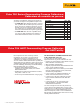
Specifications must be carefully considered when comparing calibrators from
different vendors.
For example, Fluke specifications use a 3-sigma confidence interval
(k = 3). This means that 99.7 % of measurements will remain in specifi-
cation over the stated period of time. Other manufacturers use a 2-sigma
confidence interval (k = 2). This means that 95.4 % of measurements will
remain in specification over the stated period of time so one in 20 instru-
ments are statistically likely to fail to perform to their specifications.
The most important components of a process calibrator specification are:
• Reference uncertainty. Performance of a calibrator at 23 °C + 3 °C at
the time it is verified by the manufacturer. This specification does not
include the effects of time and temperature, two of the largest
components of calibrator error.
• Time. Fluke 750 Series calibrators are delivered with both one-year
and two-year specs, to limit your calibration support costs. You choose
your cal interval based upon the performance you need.
• Temperature. Fluke process calibrator specs reflect performance from
18 °C to 28 °C. Compensation factors are provided to permit specified
use of the calibrators over a wide -10 °C to 50 °C range.
• Allowance for traceability. Fluke specs are not relative specs,
but total specs, including an allowance for uncertainty of standards
that provide traceability to national standards.
For more information, view our interpreting specifications webinar or refer to the
application note “Understanding Specifications For Process Calibrators.”
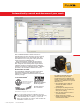
Why you can depend on Fluke calibrator specifications
9 Fluke Corporation 750 Series Brochure
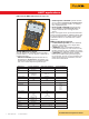
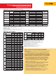
Temperature, Thermocouples
Type Source °C Measure °C Source °C
1 year 2 years 1 year 2 years
E -250 to -200 1.3 2.0 0.6 0.9
-200 to -100 0.5 0.8 0.3 0.4
-100 to 600 0.3 0.4 0.3 0.4
600 to 1000 0.4 0.6 0.2 0.3
N -200 to -100 1.0 1.5 0.6 0.9
-100 to 900 0.5 0.8 0.5 0.8
900 to 1300 0.6 0.9 0.3 0.4
J -210 to -100 0.6 0.9 0.3 0.4
-100 to 800 0.3 0.4 0.2 0.3
800 to 1200 0.5 0.8 0.3 0.3
K -200 to -100 0.7 1.0 0.4 0.6
-100 to 400 0.3 0.4 0.3 0.4
400 to 1200 0.5 0.8 0.3 0.4
1200 to 1372 0.7 1.0 0.3 0.4
T -250 to -200 1.7 2.5 0.9 1.4
-200 to 0 0.6 0.9 0.4 0.6
0 to 400 0.3 0.4 0.3 0.4
B 600 to 800 1.3 2.0 1.0 1.5
800 to 1000 1.0 1.5 0.8 1.2
1000 to 1820 0.9 1.3 0.8 1.2
R -20 to 0 2.3 2.8 1.2 1.8
0 to 100 1.5 2.2 1.1 1.7
100 to 1767 1.0 1.5 0.9 1.4
S -20 to 0 2.3 2.8 1.2 1.8
0 to 200 1.5 2.1 1.1 1.7
200 to 1400 0.9 1.4 0.9 1.4
1400 to 1767 1.1 1.7 1.0 1.5
C 0 to 800 0.6 0.9 0.6 0.9
800 to 1200 0.8 1.2 0.7 1.0
1200 to 1800 1.1 1.6 0.9 1.4
1800 to 2316 2.0 3.0 1.3 2.0
L -200 to -100 0.6 0.9 0.3 0.4
-100 to 800 0.3 0.4 0.2 0.3
800 to 900 0.5 0.8 0.2 0.3
U -200 to 0 0.6 0.9 0.4 0.6
0 to 600 0.3 0.4 0.3 0.4
Type Source °C Measure °C Source °C
1 year 2 years 1 year 2 years
BP 0 to 1000 1.0 1.5 0.4 0.6
1000 to 2000 1.6 2.4 0.6 0.9
2000 to 2500 2.0 3.0 0.8 1.2
XK -200 to 300 0.2 0.3 0.2 0.5
300 to 800 0.4 0.6 0.3 0.6
Sensor inaccuracies not included.
Accuracy with external cold junction; for internal junction add 0.2 °C
Resolution: 0.1 °C
Temperature scale: ITS-90 or IPTS-68, selectable (90 is default)
Compensation: ITS-90 per NIST Monograph 175 for B,R,S,E,J,K,N,T; IPTS-68
per IEC 584-1 for B,R,S,E,J,K,T; IPTS-68 per DIN 43710 for L,U. GOST P 8.585-
2001 for BP and XK, ASTM E988-96 for C (W5Re/W26Re)
Temperature coefficient: 0.05°C/°C (<18°C or >28°C)
0.07°C/°C for C type > 1800°C and for BP type > 2000°C
Instrument operating temperature: 0 °C to 50 °C for C and BP type
thermocouples / -10 °C to 50°C for all other types
Normal mode rejection: 65 dB at 50 Hz or 60 Hz nominal
Temperature, Resistance Temperature Detectors
Degrees or % of reading
Type (α) Range °C Measure °C 2 Source
current
Source °C Allowable
current 3
1 year 2 years 1 year 2 years
100 Ω Pt (385) -200 to 100 0.07 °C 0.14 °C 1 mA 0.05 °C 0.10 °C 0.1 mA to 10 mA
100 to 800 0.02 % + 0.05 °C 0.04 % + 0.10 °C 0.0125 % + 0.04 °C 0.025 % + 0.08 °C
200 Ω Pt (385) -200 to 100 0.07 °C 0.14 °C 500 µA 0.06 °C 0.12 °C 0.1 mA to 1 mA
100 to 630 0.02 % + 0.05 °C 0.04 % + 0.10 °C 0.017 % + 0.05 °C 0.034 % + 0.10 °C
500 Ω Pt (385) -200 to 100 0.07 °C 0.14 °C 250 µA 0.06 °C 0.12 °C 0.1 mA to 1 mA
100 to 630 0.02 % + 0.05 °C 0.04 % + 0.10 °C 0.017% + 0.05 °C 0.034 % + 0.10 °C
1000 Ω Pt (385) -200 to 100 0.07 °C 0.14 °C 150 µA 0.06 C 0.12 C 0.1 mA to 1 mA
100 to 630 0.02 % + 0.05 °C 0.04% + 0.10 °C 0.017 % + 0.05 °C 0.034 % + 0.10 °C
100 Ω Pt (3916) -200 to 100 0.07 °C 0.14 °C 1 mA 0.05 °C 0.10 °C 0.1 mA to10 mA
100 to 630 0.02 % +0.05 °C 0.04 % +0.10 °C 0.0125 % + 0.04 °C 0.025 % + 0.08 °C
100 Ω Pt (3926) -200 to 100 0.08 °C 0.16 °C 1 mA 0.05 °C 0.10 °C 0.1 mA to 10 mA
100 to 630 0.02 % +0.06 °C 0.04 % +0.12 °C 0.0125 % + 0.04 °C 0.025 % + 0.08 °C
10 Ω Cu (427) -100 to 260 0.2 °C 0.4 °C 3 mA 0.2 °C 0.4 °C 1 mA to 10 mA
120 Ω Ni (672) -80 to 260 0.1 °C 0.2 °C 1 mA 0.04 °C 0.08 °C 0.1 mA to 10 mA
1
Specifications are valid to k=3
Sensor inaccuracies not included
2
For two and three-wire RTD measurements, add 0.4°C to the specifications.
Resolution: 0.01 °C except 0.1 °C for 10 Ω Cu (427)
Temperature coefficient: 0.02 °C/°C source, (<18°C or >28°C), 0.01 °C/C for measure
Maximum input voltage: 30 V
3
Supports pulsed transmitters and PLCs with pulse times as short as 1 ms
RTD reference: Pt(385): IEC 60751, 2008; (3916): JIS C 1604, 1981 ; Pt(3926), Cu(427), Ni(672): Minco Application Aid #18