
Application Note


2 Fluke Corporation Eliminating sensor errors in loop calibrations
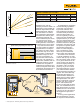
Temperature °C – Input
0 °C 400 °C
Ideal curve
Class A tolerance
Class B tolerance
Actual curve
Figure 2.
System accuracy comparison measuring 150 °C using a Pt100 (IEC751)
RTD with a transmitter span of 0 to 200 °C
Standard RTD Accuracy Characterized RTD Accuracy
Rosemount Model 644H ± 0.15 °C Rosemount Model 644H ± 0.15 °C
Standard RTD ± 1.05 °C Matched (calibrated) RTD ± 0.18 °C
Total system ± 1.06 °C Total system ± 0.23 °C
Total system accuracy calculated using RSS statistical method.
Table 1
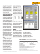
1.2
0.8
0.4
0
RSS Error ± °C
Standard Sensor Calibrated Sensor
System accuracy improved by more than 75 %!
Figure 3. System accuracy improvement achieved with a
calibrated Pt100 Sensor.
Rosemount Inc. uses the
example provided in Table 1 for
information on the possible per-
formance improvement of their
Model 644H Smart Tempera-
ture Transmitter. To achieve
this performance improvement,
the Rosemount 644H is given
information (Callendar Van
Dusen Coefficients) that allows
it to correct for the unique
performance of the temperature
sensing element, in this case a
standard IEC751 Pt100 sensor.
Dry-wells and micro-baths
are good choices for verifying
the performance of tempera-
ture probes and other related
sensors. But they do not have
the capability to calibrate the
transmitter’s output or read-
out and, by themselves, do
not allow the entire measure-
ment loop to be optimized. A
heat source, combined with an
intelligent electronic process
calibrator that is capable of
calibrating the transmitter and
readout, is required if the above
performance improvement is to
be realized and maintained.
By combining the automating
and documenting capabilities
of the Fluke 754 Document-
ing Process Calibrator with
Fluke Calibration’s intelligent
and stable family of field dry-
wells and micro-baths, you
have the capability to test the
entire loop. This combination of
equipment allows you to easily
verify the characteristics of the
temperature sensor and mea-
surement electronics. Using this
information, the entire loop can
be adjusted to optimize system
measurement performance.
Below are some examples of
how to optimize the perfor-
mance of your measurement
system using these instruments.
The Fluke 754 is connected
to a Fluke Calibration dry-well
or micro-bath by way of a serial
RS-232 interface cable. Version
2.3 or greater firmware for the
754 is required. The firmware
version is displayed briefly on
the display of the 754 during
power-up. If you do not have
the required firmware, contact
your authorized Fluke distribu-
tor for information regarding an
upgrade. The serial cable may
be obtained from either your
authorized Fluke distributor or
directly from your Fluke Calibra-
tion representative. The heat
source is connected to the 754
pressure port and is accessed
by the 754 TC/RTD source
key. Due to the length of these
tests, it is recommended that a
fully charged battery or battery
eliminator for the 754 be used.
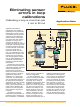
A diagram of the connection of
this equipment is pictured in
Figure 4.
In many process applications,
the instrumentation of choice
for temperature measurements
754
DOCUMENTING PROCESS CALIBRATOR
Null modem
Dry-well (3.5 mm)
Dry-well
(DB9)
2514 dry-well
interface cable
3.5 mm
interface cable
Fluke Calibration
Fluke Calibration
Fluke Calibration
Figure 4. Connecting a Fluke 754 to a Fluke Calibration dry-well.