
Application Note


3 Fluke Corporation Eliminating sensor errors in loop calibrations
is a transmitter that accepts the
output from the temperature
sensor and drives a 4-20 mA
signal back to the PLC, DCS or
indicator. This example describes
one method for verifying per-
formance and offers to optimize
this measurement to improve
performance.
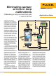
To perform this test, the RTD
sensor is removed from the
process and inserted in to the
dry-block calibrator. The mA
connections from the transmit-
ter are connected directly to
the 754 Documenting Process
Calibrator (see Figure 5). In
most applications, this solution
provides adequate performance.
But if your application includes
a uniquely-shaped sensor, you
might want to consider the use
of a micro-bath. If increased
heat source accuracy is needed,
the use of a reference thermom-
eter combined with the 754’s
User-Entered Values feature can
be used. See application note
1263925 for more information
on 754 User-Entered Values.
Once connections are made,
you are ready to acquire trans-
mitter configuration (if you
have a transmitter with HART
communications), set the test
parameters, and configure the
calibrator for mA measurement
and dry-well control as the
sourcing parameter.
Pressing the HART key on
the 754 allows the calibra-
tor to acquire the transmitter
configuration from a transmit-
ter with HART communication
capability. Following is a sample
of this acquired configuration
information.
Pressing the HART key on
the 754 again presents the
following screen with several
options for configuring the cali-
brator to the correct parameters
for this test. For the purposes
of this example, we’ll use the
transmitter configured to output
a 4-20mA signal; therefore the
correct configuration of the 754
is to measure mA and source
temperature via the dry-well.
Pressing the AS FOUND soft
key on the 754 provides access
to parameters needed to con-
figure an automated test. Below
is a typical definition that will
test the measurement system
from 50°C to 150°C sourcing
temperatures using a dry-well
in ascending order.
After the test has been
defined, the Fluke 754 will take
over and run the test record-
ing the sourced temperature,
measured output of the trans-
mitter, in mA. At the end of the
test, the results will be dis-
played on the screen, allowing
the test technician to evaluate
the results and take corrective
action if needed. Following is
Figure 5. Fluke 754 and Fluke Calibration dry-well calibrating a
4-20 mA transmitter and temperature sensor.
an example of the results.
One method of optimizing
this system to minimize error
is to shift the URV or LRV of
the transmitter to the values
measured by the 754. With a
transmitter with HART capa-
bilities, this is easily done via
the 754, by simply entering
new values in the HART SETUP