
Application Note


6 Fluke Corporation Abridged HART Transmitter Calibration
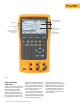
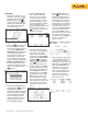
5. If the As Found test failed
(i.e., there were highlighted
errors in the error sum-
mary table), adjustment is
necessary. Press the Adjust
softkey. Select Sensor Trim
and press . (Do not select
Pressure Zero Trim. It is the
same as trimming the lower
sensor point at zero, which is
useful for pressure transmit-
ters that do not offer Sensor
Trim.) The 754 screen should
look like Figure 8.
6. Select Perform user trim –
both and press . Zero
the pressure module (vented
to atmosphere) by pressing
CLEAR
(ZERO )
. Press the Continue soft-
key and you are prompted
for the Lower Trim value. For
best results, apply the LRV
pressure and press Fetch
to load the value being
measured by the pressure
module. Press Trim. Then
press Continue to move to
the Upper Trim. As before,
apply the URV pressure,
press Fetch, and press Trim.
If the 3051 is used with the
digital PV output, skip to step
8 and perform the As Left
test. If the 4-20 mA analog
output is used in the process,
continue on to step 7.
7. Select Output Trim and
press . The value of the
primary variable (PVAO) is in
the upper right corner of the
display. This is normally a
4 mA signal. The mA value,
as constantly measured
by the Fluke 754, is in the
center of the display. Press
the Fetch softkey to load the
measured mA value. Press
Send to send the value to
Figure 8.
the 3051 to trim the output
section for the 4 mA value.
Press Continue for the
20 mA trim and repeat this
step.
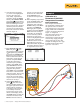
8. After completing Output Trim,
press the Done softkey and
proceed with the As Left
verification test. Press the
As Left softkey. Press Done
and then press Manual
Test. Apply the requested
pressures and press Accept
Point when the readings
are stable. On completion
an error summary table is
displayed. If none of the
errors are highlighted (Figure
9), the 3051 passes the
calibration test. If errors are
highlighted, the test has
failed and further adjustment
is required. Return to step 5
for adjustment of the 3051.
Figure 9.
Example 2
Calibration of a
Rosemount 3144 HART
Temperature Transmitter
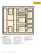
Basic connections
This example assumes that
the transmitter is isolated from
the process and is not electri-
cally connected to a loop power
supply. Make basic connections
to the 3144 per the diagram in
Figure 10. A separate
250 ohm resistor is not nec-
essary because the 754
incorporates a resistor in series
with the loop supply through
its mA jacks. The 3144 in this
example is configured for a type
K thermocouple sensor with a
span of 0 °C to 300 °C.
754
DOCUMENTING PROCESS CAL BRATOR
1
2
3
4
5
T
+
–
3144
Transmitter
TC
+
TC
–
Figure 10.