
Application Note


7 Fluke Corporation Abridged HART Transmitter Calibration
Procedure
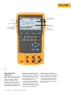
1. Power on the Fluke 754
Calibrator. Press the red
key followed by the Loop
Power softkey. Press to
bypass the warning screens
and the 754 will display the
basic HART information for
the 3144 (Figure 11).
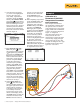
2. Press the key again and
you are prompted to select
the 754 configuration (Figure
12). Selecting MEAS mA,
SOURCE T/C typ K configures
the calibrator to measure
the analog mA output of the
transmitter and source the
correct temperature stimulus
at the 3144 input. (Selecting
MEAS PV, SOURCE T/C typ
K will configure the 754 to
evaluate the digital PV output
from the transmitter.) Press
to select.
3. Press the As Found softkey,
and then press to select
Instrument for a linear
transmitter calibration. Notice
that the calibration template
is automatically completed
with the exception of the
Tolerance. Fill in the appro-
priate test tolerance and
press the Done softkey.
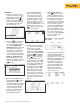
4. Press the Auto Test soft-
key to begin calibration.
Once the test is complete,
an error summary table is
displayed (Figure 13). Test
errors exceeding the toler-
ance are highlighted. When
done viewing the table,
press the Done softkey. Press
Done again to accept, or
to change the tag, serial
number or ID fields.
5. If the As Found test failed
(i.e., there were highlighted
errors in the error sum-
mary table), adjustment is
necessary. Press the Adjust
softkey. Select Sensor Trim
and press . Select Per-
form user trim – both and
press . The 754 screen
should look like Figure 14.
6. For best results, press LRV to
apply the LRV for the Lower
Trim value. Press Trim and
then Continue to move to
the Upper Trim. Press URV,
press Trim, and then press
Done. If the 3144 is used
with the digital PV output,
skip to step 8 and perform
the As Left test. If the analog
4-20 mA output is used in
the process, continue on to
step 7.
Figure 11.
7. Select Output Trim and
press . The value of the
primary variable (PVAO) is
in the upper right corner of
the display. (Figure 5). This
is normally a 4 mA signal.
The mA value, as constantly
measured by the Fluke 754,
is in the center of the dis-
play. Press the Fetch softkey
to load the measured mA
value. Press Send to send
the value to the 3144 to trim
the output section for the
4 mA value. Press Continue
for the 20 mA trim and
repeat this step.
8. After completing Output Trim,
press the Done softkey and
proceed with the As Left
verification test. Press the As
Left softkey. Press Done and
then press Auto Test. On
completion, an error sum-
mary table is displayed. If
errors are highlighted, the
test has failed and further
adjustment is required.
Return to step 5 for adjust-
ment of the 3144.
Figure 12.
Figure 13.
Figure 14.
Figure 15.
Figure 16.